Infiniti QX56 (Z62). Manual - part 338


  Index      Infiniti     Infiniti QX56 (Z62) - service repair manual 2011 year


Search            


Content   ..  336  337  338  339   ..


Infiniti QX56 (Z62). Manual - part 338


DAS

WARNING SYSTEMS SWITCH CIRCUIT

DAS-389

< DTC/CIRCUIT DIAGNOSIS >

[LDW & LDP]

C

D

E

F

G

H

I

J

K

L

M

B

N

P

A

WARNING SYSTEMS SWITCH CIRCUIT

Component Function Check

INFOID:0000000006223825

1.

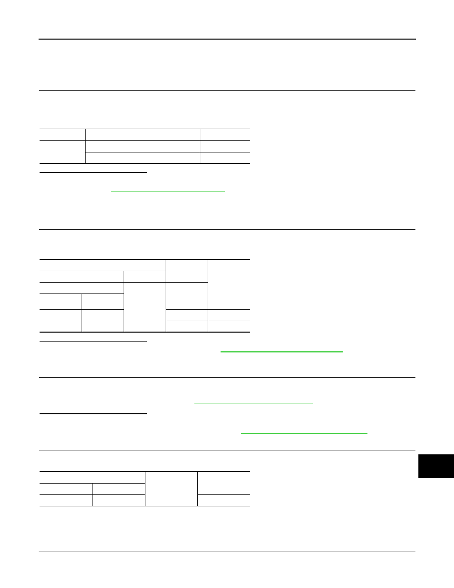
CHECK WARNING SYSTEMS SWITCH INPUT SIGNAL

1.

Turn the ignition switch ON.

2.

Select the DATA MONITOR item “WARN SYS SW” of “ICC/ADAS” with CONSULT-III.

3.

With operating the warning systems switch, check the monitor status.

Is the inspection result normal?

YES

>> Warning systems switch circuit is normal.

NO

>> Refer to 

DAS-389, "Diagnosis Procedure"

.

Diagnosis Procedure

INFOID:0000000006223826

1.

CHECK WARNING SYSTEMS SWITCH SIGNAL INPUT

1.

Turn the ignition switch ON.

2.

Check voltage between ADAS control unit harness connector and ground.

Is the inspection result normal?

YES

>> Replace the ADAS control unit. Refer to 

DAS-63, "Removal and Installation"

.

NO

>> GO TO 2.

2.

CHECK WARNING SYSTEMS SWITCH

1.

Turn ignition switch OFF.

2.

Remove warning systems switch.

3.

Check warning systems switch. Refer to 

DAS-390, "Component Inspection"

.

Is the inspection result normal?

YES

>> GO TO 3.

NO

>> Replace the warning systems switch. Refer to 

DAS-404, "Removal and Installation"

.

3.

CHECK WARNING SYSTEMS SWITCH GROUND CIRCUIT

Check continuity between twin switch harness connector terminal and the ground.

Is the inspection result normal?

YES

>> GO TO 4.

NO

>> Repair harness or connector.

4.

CHECK WARNING SYSTEMS SWITCH SIGNAL INPUT CIRCUIT FOR OPEN

1.

Disconnect the ADAS control unit connector.

Monitor item

Condition

Monitor status

WARN SYS 
SW

Warning systems switch is pressed

On

Warning systems switch is not pressed

OFF

Terminals

Condition

Voltage

(Approx.)

(+)

(

)

ADAS control unit

Ground

Warning 
systems 

switch

Connector

Terminal

B61

1

Pressed

0 V

Released

12 V

Twin switch 

Ground

Continuity

Connector

Terminal

M127

3

Existed

DAS-390

< DTC/CIRCUIT DIAGNOSIS >

[LDW & LDP]

WARNING SYSTEMS SWITCH CIRCUIT

2.

Check continuity between the ADAS control unit harness connector and twin switch harness connector.

Is the inspection result normal?

YES

>> GO TO 5.

NO

>> Repair the harnesses or connectors.

5.

CHECK WARNING SYSTEMS SWITCH SIGNAL INPUT CIRCUIT FOR SHORT

Check continuity between the ADAS control unit harness connector and ground.

Is the inspection result normal?

YES

>> Replace the ADAS control unit. Refer to 

DAS-63, "Removal and Installation"

.

NO

>> Repair the harnesses or connectors.

Component Inspection

INFOID:0000000006223827

1.

CHECK WARNING SYSTEMS SWITCH

Check continuity of warning systems switch.

Is the inspection result normal?

YES

>> INSPECTION END

NO

>> Replace warning systems switch.

ADAS control unit

Twin switch

Continuity

Connector

Terminal

Connector

Terminal

B61

1

M127

2

Existed

ADAS control unit

Ground

Continuity

Connector

Terminal

B61

1

Not existed

Terminal

Condition

Continuity

2

3

When warning systems switch is pressed

Existed

When warning systems switch is released

Not existed

DAS

WARNING SYSTEMS ON INDICATOR CIRCUIT

DAS-391

< DTC/CIRCUIT DIAGNOSIS >

[LDW & LDP]

C

D

E

F

G

H

I

J

K

L

M

B

N

P

A

WARNING SYSTEMS ON INDICATOR CIRCUIT

Component Function Check

INFOID:0000000006223828

1.

CHECK WARNING SYSTEMS ON INDICATOR

1.

Turn the ignition switch ON.

2.

Select the active test item “WARNING SYSTEM IND” of “ICC/ADAS” with CONSULT-III.

3.

With operating the test item, check the operation.

Is the inspection result normal?

YES

>> INSPECTION END

NO

>> Refer to 

DAS-391, "Diagnosis Procedure"

.

Diagnosis Procedure

INFOID:0000000006223829

1.

CHECK WARNING ON INDICATOR POWER SUPPLY CIRCUIT

1.

Turn ignition switch OFF.

2.

Disconnect twin switch connector.

3.

Turn ignition switch ON.

4.

Check voltage between twin switch harness connector and ground.

Is the inspection result normal?

YES

>> GO TO 2.

NO

>> Repair the warning systems ON indicator power supply circuit.

2.

CHECK WARNING SYSTEMS ON INDICATOR SIGNAL FOR OPEN

1.

Turn ignition switch OFF.

2.

Disconnect the ADAS control unit harness connector.

3.

Check continuity between the ADAS control unit harness connector and twin switch harness connector.

Is the inspection result normal?

YES

>> GO TO 3.

NO

>> Repair the harnesses or connectors.

3.

CHECK WARNING SYSTEMS ON INDICATOR SIGNAL CIRCUIT FOR SHORT

Check continuity between the ADAS control unit harness connector and ground.

Is the inspection result normal?

YES

>> GO TO 4.

On

: Warning systems ON indicator illuminates

Off

: Warning systems ON indicator is turned OFF

Terminals

Voltage

(Approx.)

(+)

(

)

Twin switch

Ground

Connector

Terminal

M127

8

Battery voltage

ADAS control unit

Twin switch

Continuity

Connector

Terminal

Connector

Terminal

B61

4

M127

9

Existed

ADAS control unit

Ground

Continuity

Connector

Terminal

B61

4

Not existed

DAS-392

< DTC/CIRCUIT DIAGNOSIS >

[LDW & LDP]

WARNING SYSTEMS ON INDICATOR CIRCUIT

NO

>> Repair the harnesses or connectors.

4.

CHECK WARNING SYSTEMS ON INDICATOR

Check the warning systems ON indicator. Refer to 

DAS-392, "Component Inspection"

.

Is the inspection result normal?

YES

>> Replace the ADAS control unit. Refer to 

DAS-63, "Removal and Installation"

.

NO

>> Replace warning systems switch. 

DAS-404, "Removal and Installation"

.

Component Inspection

INFOID:0000000006223830

1.

CHECK WARNING SYSTEMS ON INDICATOR

Apply battery voltage to warning systems switch terminals 8 and 9, and then check if the warning systems ON
indicator illuminates.

Is the inspection result normal?

YES

>> INSPECTION END

NO

>> Replace the warning systems switch. Refer to 

DAS-404, "Removal and Installation"

.

Terminals

Condition

Driver warning 

systems ON in-

dicator

(+)

(-)

8

9

When the battery voltage is applied

On

When the battery voltage is not applied

Off


Content   ..  336  337  338  339   ..