Infiniti QX56 (Z62). Manual - part 196
CCS
ADAS CONTROL UNIT
CCS-51
< ECU DIAGNOSIS INFORMATION >
[ICC]
C
D
E
F
G
H
I
J
K
L
M
B
N
P
A
- CRNT: A malfunction is detected now
- PAST: A malfunction was detected in the past
• IGN counter is displayed on FFD (Freeze Frame Data).
- 0: The malfunctions that are detected now
CAN communication system (U1000, U1010)
- 1 - 39: It increases like 0
→
1
→
2 ··· 38
→
39 after returning to the normal condition whenever the ignition
switch OFF
→
ON. It returns to 0 when a malfunction is detected again in the process.
- If it is over 39, it is fixed to 39 until the self-diagnosis results are erased.
Other than CAN communication system (Other than U1000, U1010)
- 1 - 49: It increases like 0
→
1
→
2 ··· 38
→
49 after returning to the normal condition whenever the ignition
switch OFF
→
ON. It returns to 0 when a malfunction is detected again in the process.
- If it is over 49, it is fixed to 49 until the self-diagnosis results are erased.
Systems for fail-safe
• A: Vehicle-to-vehicle distance control mode
• B: Conventional (fixed speed) cruise control mode
• C: Intelligent Brake Assist (IBA)
• D: Forward Collision Warning (FCW)
• E: Distance Control Assist (DCA)
• F: Lane Departure Warning (LDW)/Lane Departure Prevention (LDP)
• G: Blind Spot Warning (BSW)
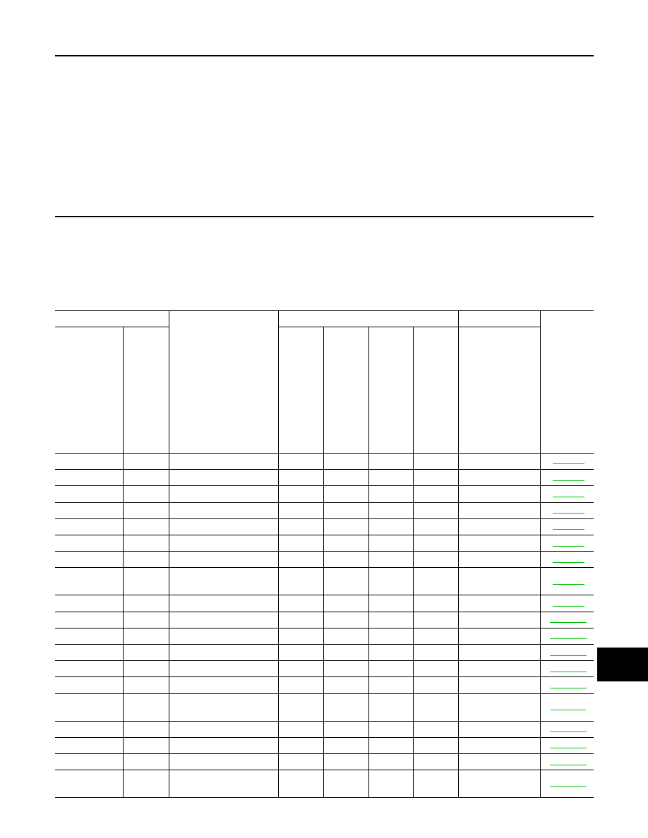
DTC
CONSULT-III display
Warning lamp
Fail-safe
Reference
CONSULT-III
On board
display
ICC system warning lamp
IBA OFF
indicat
o
r l
a
mp
La
ne
de
p
a
rtu
re wa
rni
n
g
la
mp
BSW w
a
rni
n
g
lamp
Sy
st
e
m
C1A00
0
CONTROL UNIT
ON
ON
ON
ON
A, B, C, D, E, F, G
C1A01
1
POWER SUPPLY CIR
ON
ON
ON
ON
A, B, C, D, E, F, G
C1A02
2
POWER SUPPLY CIR 2
ON
ON
ON
ON
A, B, C, D, E, F, G
C1A03
3
VHCL SPEED SE CIRC
ON
ON
ON
ON
A, B, C, D, E, F, G
C1A04
4
ABS/TCS/VDC CIRC
ON
ON
ON
A, B, C, D, E, F
C1A05
5
BRAKE SW/STOP L SW
ON
ON
ON
A, B, C, D, E, F
C1A06
6
OPERATION SW CIRC
ON
ON
A, B, E, F
C1A12
12
LASER BEAM OFFCN-
TR
ON
ON
A, C, D, E
C1A13
13
STOP LAMP RLY FIX
ON
ON
A, B, C, D, E
C1A14
14
ECM CIRCUIT
ON
ON
A, B, E, F
C1A15
15
GEAR POSITION
ON
ON
ON
ON
A, B, C, D, E, F, G
C1A16
16
RADAR STAIN
ON
ON
A, C, D, E
C1A17
17
ICC SENSOR MALF
ON
ON
A, B, C, D, E
C1A18
18
LASER AIMING INCMP
ON
ON
A, C, D, E
C1A21
21
ICC SENSOR HIGH
TEMP
ON
ON
A, B, C, D, E
C1A24
24
NP RANGE
ON
ON
ON
ON
A, B, C, D, E, F, G
C1A26
26
ECD MODE MALF
ON
ON
A, B, C, D, E
C1A27
27
ECD PWR SUPLY CIR
ON
ON
A, B, C, D, E
C1A33
33
CAN TRANSMISSION
ERR
ON
A, B, E