Infiniti QX56 (Z62). Manual - part 1340


  Index      Infiniti     Infiniti QX56 (Z62) - service repair manual 2011 year


Search            


Content   ..  1338  1339  1340  1341   ..


Infiniti QX56 (Z62). Manual - part 1340


TRANSMISSION ASSEMBLY

TM-269

< UNIT DISASSEMBLY AND ASSEMBLY >

[7AT: RE7R01B]

C

E

F

G

H

I

J

K

L

M

A

B

TM

N

O

P

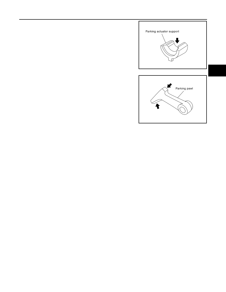
If the contact surface on parking actuator support and parking pawl
has excessive wear, abrasion, bend or any other damage, replace
the components.

SCIA5143E

SCIA5144E

TM-270

< UNIT DISASSEMBLY AND ASSEMBLY >

[7AT: RE7R01B]

OIL PUMP, 2346 BRAKE, FRONT BRAKE PISTON

OIL PUMP, 2346 BRAKE, FRONT BRAKE PISTON

Exploded View

INFOID:0000000006226920

Disassembly

INFOID:0000000006226921

1.

Remove snap ring (1) from oil pump assembly using a flat-
bladed screwdriver (A).

CAUTION:

• Be careful not to scratch oil pump cover and 2346 brake

retaining plate.

• Be careful not to damage snap ring.

1.

Oil pump housing oil seal

2.

Oil pump housing

3.

O-ring

4.

Oil pump cover

5.

O-ring

6.

D-ring

7.

D-ring

8.

Front brake piston

9.

Front brake spring retainer

10. Snap ring

11.

D-ring

12. D-ring

13. 2346 brake piston

14. 2346 brake spring retainer

15. Snap ring

16. Seal ring

17. Dish plate

18. Driven plate

19. Drive plate

20. Retaining plate

21. Snap ring

: Apply Liquid Gasket (Three Bond 1215) or equivalent.

Refer to 

GI-4, "Components"

 for symbols not described on the above.

JPDIA1089GB

JPDIA1090ZZ

OIL PUMP, 2346 BRAKE, FRONT BRAKE PISTON

TM-271

< UNIT DISASSEMBLY AND ASSEMBLY >

[7AT: RE7R01B]

C

E

F

G

H

I

J

K

L

M

A

B

TM

N

O

P

2.

Remove 2346 brake component part (retaining plate, drive
plate, driven plate, and dish plate) (1) from oil pump assembly.

3.

Remove seal ring (1) from oil pump assembly.

4.

Set the clutch spring compressor (SST: KV31103800) (A) on
front brake spring retainer and remove snap ring (fixing front
brake spring retainer) (1) from oil pump assembly while com-
pressing return spring.

CAUTION:

Be careful not to expand snap ring excessively.

5.

Remove front brake spring retainer (1) from oil pump assembly.

6.

Set the clutch spring compressor [SST: KV31102400 (J-34285
and J-34285-87)] (A) on 2346 brake spring retainer and remove
snap ring (fixing 2346 brake spring retainer) (1) from oil pump
assembly while compressing return spring.

CAUTION:

Be careful not to expand snap ring excessively.

JPDIA1091ZZ

JPDIA1092ZZ

JSDIA1729ZZ

JPDIA1094ZZ

B

:  Press

JSDIA1730ZZ

TM-272

< UNIT DISASSEMBLY AND ASSEMBLY >

[7AT: RE7R01B]

OIL PUMP, 2346 BRAKE, FRONT BRAKE PISTON

7.

Remove 2346 brake spring retainer (1) from oil pump assembly.

8.

Remove front brake piston (1) from oil pump assembly with
compressed air. Refer to 

TM-222, "Oil Channel"

.

CAUTION:

Care should be taken not to abruptly blow air. It makes pis-
ton incline, as the result, it becomes hard to disassemble
the piston.

9.

Remove D-ring (inner) (1) and D-ring (outer) (2) from front brake
piston.

JPDIA1096ZZ

A

: Front brake pressure hole

JPDIA1097ZZ

JPDIA1098ZZ


Content   ..  1338  1339  1340  1341   ..