Content .. 1308 1309 1310 1311 ..
Infiniti QX56 (Z62). Manual - part 1310
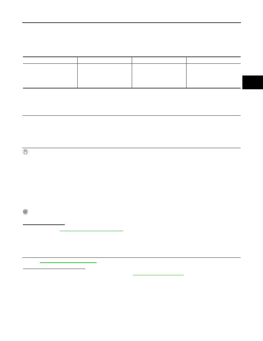
P2731 PRESSURE CONTROL SOLENOID F
TM-149
< DTC/CIRCUIT DIAGNOSIS >
[7AT: RE7R01B]
C
E
F
G
H
I
J
K
L
M
A
B
TM
N
O
P
P2731 PRESSURE CONTROL SOLENOID F
DTC Logic
INFOID:0000000006226871
DTC DETECTION LOGIC
DTC CONFIRMATION PROCEDURE
CAUTION:
Always drive vehicle at a safe speed.
1.
PRECONDITIONING
If “DTC CONFIRMATION PROCEDURE” is previously conducted, always turn ignition switch OFF and wait at
least 10 seconds before performing the next test.
>> GO TO 2.
2.
CHECK DTC DETECTION
With CONSULT-III
1.
Start the engine.
2.
Select “BATTERY VOLT”, “MANU MODE SW”, “GEAR” and “VHCL/S SE-A/T” in “Data Monitor” in
“TRANSMISSION”.
3.
Drive vehicle and maintain the following conditions for 5 seconds or more.
4.
Perform “Self Diagnostic Results” in “TRANSMISSION”.
With GST
Follow the procedure “With CONSULT-III”.
Is “P2731” detected?
YES
>> Go to
NO
>> INSPECTION END
Diagnosis Procedure
INFOID:0000000006226872
1.
CHECK INTERMITTENT INCIDENT
GI-40, "Intermittent Incident"
.
Is the inspection result normal?
YES
>> Replace the control valve & TCM. Refer to
.
NO
>> Repair or replace damaged parts.
DTC
Trouble diagnosis name
DTC is detected if...
Possible cause
P2731
Pressure Control Solenoid F
The 2346 brake solenoid valve
monitor value is 0.4 A or less
when the 2346 brake solenoid
valve command value is more
than 0.75 A.
• Harness or connectors
(Solenoid valve circuit is
open or shorted.)
• 2346 brake solenoid valve
BATTERY VOLT
: 9 V or more
MANU MODE SW
: ON
GEAR
: 2nd
VHCL/S SE-A/T
: 10 km/h (7 MPH) or more