Infiniti QX56 (Z62). Manual - part 1298


  Index      Infiniti     Infiniti QX56 (Z62) - service repair manual 2011 year


Search            


Content   ..  1296  1297  1298  1299   ..


Infiniti QX56 (Z62). Manual - part 1298


A/T POSITION

TM-101

< BASIC INSPECTION >

[7AT: RE7R01B]

C

E

F

G

H

I

J

K

L

M

A

B

TM

N

O

P

A/T POSITION

Inspection

INFOID:0000000006226794

1.

Place selector lever in “P” position, and turn ignition switch ON (engine stop).

2.

Check that selector lever can be shifted to other than “P” position when brake pedal is depressed. Also
check that selector lever can be shifted from “P” position only when brake pedal is depressed.

3.

Shift the selector lever and check for excessive effort, sticking, noise or rattle.

4.

Confirm that the selector lever stops at each position by feeling the engagement when it is moved through
all the positions. Check whether or not the actual position the selector lever matches the position shown
by the shift position indicator and the A/T body.
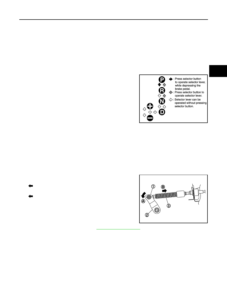
5.

The method of operating the lever to individual positions cor-
rectly is shown in the figure.

6.

When selector button is pressed in “P”, “R”, or “N” position with-
out applying forward/backward force to selector lever, check but-
ton operation for sticking.

7.

Confirm that the back-up lamps illuminate only when lever is
placed in the “R” position. Confirm that the back-up lamps do not
illuminate when selector lever is pushed against “R” position in
the “P” or “N” position.

8.

Confirm that the engine can only be started with the selector
lever in the “P” and “N” positions. (With selector lever in the “P”
position, engine can be started even when selector lever is
moved forward and backward.)

9.

Make sure that A/T is locked completely in “P” position.

10. When selector lever is set to manual shift gate, make sure that manual mode is displayed on combination

meter.
In addition, a set shift position must be changed when the selector lever is shifted to the “+” or “

” side in

the manual mode. (Only while driving.)

Adjustment

INFOID:0000000006379166

1.

Shift selector lever in “P” position.

2.

Loosen nut (1).

3.

Turn the manual lever (2) all the way in the “P” range direction
[


(A)].

4.

Hold and push the control cable (3) in the vehicle front direction
[

 (B)], and tighten the nut by hand with cable set in free condi-

tion.

CAUTION:

Be careful not put any load to manual lever.
NOTE:
Press control cable with a force of 9.8 N (approximately 1 kg, 2.2
lb).

5.

Tighten nut to specified torque. Refer to 

TM-178, "Exploded View"

.

JSDIA0790GB

JSDIA1587ZZ

TM-102

< DTC/CIRCUIT DIAGNOSIS >

[7AT: RE7R01B]

U0300 CAN COMMUNICATION DATA

DTC/CIRCUIT DIAGNOSIS

U0300 CAN COMMUNICATION DATA

Description

INFOID:0000000006226795

The amount of data transmitted from each control unit is read.

DTC Logic

INFOID:0000000006226796

DTC DETECTION LOGIC

DTC CONFIRMATION PROCEDURE

1.

PRECONDITIONING

If “DTC CONFIRMATION PROCEDURE” has been previously conducted, always turn ignition switch OFF and
wait at least 10 seconds before conducting the next test.

>> GO TO 2.

2.

CHECK DTC DETECTION

 With CONSULT-III

1.

Turn ignition switch ON and wait 2 seconds or more.

2.

Perform “Self Diagnostic Results” in “TRANSMISSION”.

Is “U0300” detected?

YES

>> Go to 

TM-102, "Diagnosis Procedure"

.

NO

>> INSPECTION END

Diagnosis Procedure

INFOID:0000000006226797

1.

CHECK CONTROL UNIT

Check the number of control units replaced before detecting “U0300”.

Is the number of replaced control units one?

YES

>> Since the replaced control unit may be out of specifications, check the part number and specifica-

tions.

NO

>> GO TO 2.

2.

INSPECTION CONTROL UNIT

 With CONSULT-III

1.

Remove one of the replaced control units.

2.

Install the previous control unit mounted before replacement.

3.

Turn ignition switch ON and wait 2 seconds or more.

4.

Perform “Self Diagnostic Results” in “TRANSMISSION”.

Is “U0300” detected?

YES

>> Turn OFF the ignition switch to check the other control units in the same method.

NO

>> Since the removed control unit may be out of specifications, check the part number and specifica-

tions.

DTC

Trouble diagnosis name

DTC is detected if...

Possible cause

U0300

Internal Control Module Soft-
ware Incompatibility

When the amount of data trans-
mitted from each control unit is 
smaller than the specified 
amount.

Control units other than TCM.

U1000 CAN COMM CIRCUIT

TM-103

< DTC/CIRCUIT DIAGNOSIS >

[7AT: RE7R01B]

C

E

F

G

H

I

J

K

L

M

A

B

TM

N

O

P

U1000 CAN COMM CIRCUIT

Description

INFOID:0000000006226798

CAN (Controller Area Network) is a serial communication line for real-time application. It is an on-vehicle mul-
tiplex communication line with high data communication speed and excellent malfunction detection ability.
Many electronic control units are equipped onto a vehicle, and each control unit shares information and links
with other control units during operation (not independently). In CAN communication, control units are con-
nected with 2 communication lines (CAN-H line, CAN-L line) allowing a high rate of information transmission
with less wiring. Each control unit transmits/receives data but selectively reads required data only.

DTC Logic

INFOID:0000000006226799

DTC DETECTION LOGIC

DTC CONFIRMATION PROCEDURE

1.

PRECONDITIONING

If “DTC CONFIRMATION PROCEDURE” is previously conducted, always turn ignition switch OFF and wait at
least 10 seconds before performing the next test.

>> GO TO 2.

2.

CHECK DTC DETECTION

 With CONSULT-III

1.

Start the engine.

2.

Run engine for at least 2 consecutive seconds at idle speed.

3.

Perform “Self Diagnostic Results” in “TRANSMISSION”.

 With GST

Follow the procedure “With CONSULT-III”

Is “U1000” detected?

YES

>> Go to 

TM-103, "Diagnosis Procedure"

.

NO

>> INSPECTION END

Diagnosis Procedure

INFOID:0000000006226800

Go to 

LAN-18, "Trouble Diagnosis Flow Chart"

.

DTC

Trouble diagnosis name

DTC is detected if...

Possible cause

U1000

CAN Communication Line

TCM is not transmitting or re-
ceiving CAN communication 
signal for 2 seconds or more.

• Harness or connectors

(CAN communication line is 
open or shorted.)

• TCM

TM-104

< DTC/CIRCUIT DIAGNOSIS >

[7AT: RE7R01B]

P0615 STARTER RELAY

P0615 STARTER RELAY

Description

INFOID:0000000006226801

TCM prohibits cranking other than at “P” or “N” position.

DTC Logic

INFOID:0000000006226802

DTC DETECTION LOGIC

DTC CONFIRMATION PROCEDURE

1.

PRECONDITIONING

If “DTC CONFIRMATION PROCEDURE” is previously conducted, always turn ignition switch OFF and wait at
least 10 seconds before performing the next test.

>> GO TO 2.

2.

CHECK DTC DETECTION

 With CONSULT-III

1.

Shift the selector lever to “P” and “N” positions.

2.

Turn ignition switch ON and wait 2 seconds or more.

3.

Perform “Self Diagnostic Results” in “TRANSMISSION”.

Is “P0615” detected?

YES

>> Go to 

TM-104, "Diagnosis Procedure"

.

NO

>> INSPECTION END

Diagnosis Procedure

INFOID:0000000006226803

1.

CHECK STARTER RELAY SIGNAL

1.

Turn ignition switch ON.

2.

Check voltage between IPDM E/R connector terminal and ground.

Is the inspection result normal?

YES

>> Check starter relay circuit. Refer to 

STR-7, "Wiring Diagram"

.

NO

>> GO TO 2.

2.

 CHECK HARNESS BETWEEN A/T ASSEMBLY AND IPDM E/R (PART 1)

1.

Turn ignition switch OFF.

2.

Disconnect A/T assembly connector and IPDM E/R connector.

3.

Check the continuity between A/T assembly vehicle side harness connector terminal and IPDM E/R vehi-
cle side harness connector terminal.

DTC

Trouble diagnosis name

DTC is detected if...

Possible cause

P0615

Starter Relay Circuit

The starter monitor value is 
OFF when the ignition switch is 
ON at the “P” and “N” positions.

• Harness or connectors

(Starter relay and TCM circuit 
is open or shorted.)

• Starter relay circuit

IPDM E/R connector

Ground

Condition

Voltage (Approx.)

Connector

Terminal

E15

48

Selector lever in “P” and 
“N” positions.

Battery voltage

Selector lever in other 
positions.

0 V


Content   ..  1296  1297  1298  1299   ..