Infiniti QX56 (Z62). Manual - part 1264


  Index      Infiniti     Infiniti QX56 (Z62) - service repair manual 2011 year


Search            


Content   ..  1262  1263  1264  1265   ..


Infiniti QX56 (Z62). Manual - part 1264


STC-8

< ECU DIAGNOSIS INFORMATION >

POWER STEERING CONTROL UNIT

ECU DIAGNOSIS INFORMATION

POWER STEERING CONTROL UNIT

Reference Value 

INFOID:0000000006256121
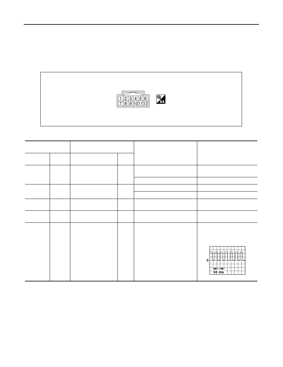
TERMINAL LAYOUT

PHYSICAL VALUES

JSGIA0023ZZ

Terminal No.

(Wire color)

Description

Condition

Value (Approx.)

+

-

Signal name

Input/

Output

1

(R)

Ground

Power steering solenoid 
valve control voltage

Output

Vehicle speed: 0 km/h (0 MPH)
(Engine is running)

4.4 – 6.6 V

Vehicle speed: 100 km/h (62 MPH)

2.4 – 3.6 V

3

(GR)

Ground

Ignition switch power 
supply

Input

Ignition switch: ON

Battery voltage

Ignition switch: OFF

0 V

5

(L)

Ground

Power steering solenoid 
valve ground

Always

0  V

6

(B)

Ground

Ground

Always

0 V

8

(SB)

Ground

Vehicle speed signal

Input

Vehicle speed: 40 km/h (25 MPH)

CAUTION:

Check air pressure of tire under 
standard condition.

NOTE:
The maximum voltage varies de-
pending on the specification 
(destination unit).

JSNIA0015GB

POWER STEERING CONTROL UNIT

STC-9

< ECU DIAGNOSIS INFORMATION >

C

D

E

F

H

I

J

K

L

M

A

B

STC

N

O

P

CAUTION:

When using circuit tester or oscilloscope to measure voltage for inspection, be sure not to forcibly
extend any connector terminals.

Fail-Safe 

INFOID:0000000006256122

EPS system

• EPS system enters the fail-safe mode (that allows the steering

force to be controlled without impairing the drivability) if any of the
input/output values to/from EPS system (power steering control
unit) deviate from the standard range.

• The power steering control unit controls the driving voltage to the

power steering solenoid valve for maintaining the power steering
assist force when the fail-safe function is activated. (The engine
speed signals control EPS system if any vehicle speed signal error
is detected.)

10

(B/SB)

Ground

Engine speed signal

Input

Engine is running
• Warm-up condition
• Idle speed

Engine is running
• Warm-up condition
• Engine speed: Approx. 2,000 

rpm

Terminal No.

(Wire color)

Description

Condition

Value (Approx.)

+

-

Signal name

Input/

Output

JPBIA3352ZZ

JPBIA3354ZZ

JPGIB0022GB

Error area and root cause

Cancel condition

Engine speed is 1,500 rpm or more and there is no vehicle speed signal input for 
over 10 seconds during vehicle travel.

• When a vehicle speed signal of 2 km/h (1.2 

MPH) or more is inputted.

• Ignition switch is turned OFF to ON.

Vehicle speed signal has abruptly dropped from 30 km/h (19 MPH) or more to 2 
km/h (1.2 MPH) or less within 1.4 seconds.

STC-10

< WIRING DIAGRAM >

ELECTRONICALLY CONTROLLED POWER STEERING SYSTEM

WIRING DIAGRAM

ELECTRONICALLY CONTROLLED POWER STEERING SYSTEM 

Wiring Diagram 

INFOID:0000000006256123

JCGWM0392GB

ELECTRONICALLY CONTROLLED POWER STEERING SYSTEM

STC-11

< WIRING DIAGRAM >

C

D

E

F

H

I

J

K

L

M

A

B

STC

N

O

P

JCGWM0393GB


Content   ..  1262  1263  1264  1265   ..