Infiniti QX56 (Z62). Manual - part 1186


  Index      Infiniti     Infiniti QX56 (Z62) - service repair manual 2011 year


Search            


Content   ..  1184  1185  1186  1187   ..


Infiniti QX56 (Z62). Manual - part 1186


SEC-134

< DTC/CIRCUIT DIAGNOSIS >

[WITH INTELLIGENT KEY SYSTEM]

B210E STARTER RELAY

B210E STARTER RELAY

DTC Logic

INFOID:0000000006226298

DTC DETECTION LOGIC

NOTE:
• If DTC B210E is displayed with DTC U1000, first perform the trouble diagnosis for DTC U1000. Refer to

PCS-28, "DTC Logic"

.

• If DTC B210E is displayed with DTC B2605, first perform the trouble diagnosis for DTC B2605. Refer to

SEC-91, "DTC Logic"

.

• When IPDM E/R power supply voltage is low (Approx. 7 - 8 V for about 1 second), the DTC B210E may be

detected.

DTC CONFIRMATION PROCEDURE

1.

PERFORM DTC CONFIRMATION PROCEDURE

1.

Press push-button ignition switch under the following conditions to start engine, and wait 1 second or
more.

-

Selector lever: In the P position

-

Brake pedal: Depressed

2.

Check DTC in “Self Diagnostic Result” mode of “IPDM E/R” using CONSULT-III.

Is DTC detected?

YES

>> Go to 

SEC-134, "Diagnosis Procedure"

.

NO

>> INSPECTION END

Diagnosis Procedure

INFOID:0000000006226299

1.

CHECK STARTER RELAY OUTPUT SIGNAL

1.

Check voltage between BCM harness connector and ground.

Is the inspection result normal?

YES

>> GO TO 3.

NO

>> GO TO 2.

2.

CHECK STARTER RELAY OUTPUT SIGNAL CIRCUIT

1.

Turn ignition switch OFF.

2.

Disconnect BCM connector.

3.

Disconnect IPDM E/R connector.

4.

Check continuity between BCM harness connector and IPDM E/R harness connector.
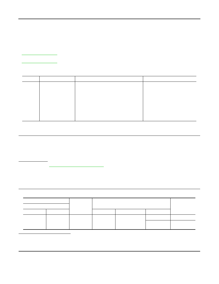
DTC No.

Trouble diagnosis name

DTC detecting condition

Possible cause

B210E

STARTER RELAY OFF

When comparing the following items, IPDM E/R 
detects that starter relay is stuck in the OFF posi-
tion for 1 second or more.
• Starter control relay signal (CAN) from BCM
• Starter relay status signal (CAN) from BCM
• Starter control relay and starter relay status 

signal (IPDM E/R input)

• Starter control relay control signal (IPDM E/R 

output)

• P/N position signal input

• Harness or connector

(CAN communication line is open or 
shorted.)

• Harness or connector

(Starter relay circuit is open or 
shorted.)

• IPDM  E/R
• BCM
• Battery

(+)

(–)

Condition

Voltage (V)

(Approx.)

BCM

Connector

Terminal

Ignition switch

Brake pedal

Selector lever

M71

97

Ground

ON

Depressed

P or N

12

Other than 

above

0

B210E STARTER RELAY

SEC-135

< DTC/CIRCUIT DIAGNOSIS >

[WITH INTELLIGENT KEY SYSTEM]

C

D

E

F

G

H

I

J

L

M

A

B

SEC

N

O

P

5.

Check continuity between BCM harness connector and ground.

Is the inspection result normal?

YES

>> Replace IPDM E/R. Refer to 

PCS-32, "Removal and Installation"

.

NO

>> Repair or replace harness.

3.

CHECK STARTER RELAY CIRCUIT

1.

Turn ignition switch OFF.

2.

Disconnect IPDM E/R connector.

3.

Check voltage between IPDM E/R harness connector and ground.

Is the inspection result normal?

YES

>> GO TO 4.

NO

>> Check harness for open or short between IPDM E/R and battery. Refer to 

STR-7, "Wiring Dia-

gram"

.

4.

REPLACE BCM

1.

Replace BCM. Refer to 

BCS-81, "Removal and Installation"

.

2.

Perform DTC CONFIRMATION PROCEDIURE for DTC B210E. Refer to 

SEC-134, "DTC Logic"

.

Is the inspection result normal?

YES

>> INSPECTION END

NO

>> Replace IPDM E/R. Refer to 

PCS-32, "Removal and Installation"

.

BCM

IPDM E/R

Continuity

Connector

Terminal

Connector

Terminal

M71

97

E13

30

Existed

BCM

Ground

Continuity

Connector

Terminal

M71

97

Not existed

(+)

(–)

Voltage (V)

(Approx.)

IPDM E/R

Connector

Terminal

E10

4

Ground

Battery voltage

SEC-136

< DTC/CIRCUIT DIAGNOSIS >

[WITH INTELLIGENT KEY SYSTEM]

B210F SHIFT POSITION/CLUTCH INTERLOCK SWITCH

B210F SHIFT POSITION/CLUTCH INTERLOCK SWITCH

DTC Logic

INFOID:0000000006226300

DTC DETECTION LOGIC

NOTE:
If DTC B210F is displayed with DTC U1000, first perform the trouble diagnosis for DTC U1000. Refer to 

PCS-

28, "DTC Logic"

.

DTC CONFIRMATION PROCEDURE

1.

PERFORM DTC CONFIRMATION PROCEDURE

1.

Shift selector lever to the P position. 

2.

Turn ignition switch ON and wait 1 second or more.

3.

Shift selector lever to the N position and wait 1 second or more. 

4.

Shift selector lever to any position other than P and N, and wait 1 second or more. 

5.

Check DTC in “Self Diagnostic Result” mode of “IPDM E/R” using CONSULT-III.

Is DTC detected?

YES

>> Go to 

SEC-136, "Diagnosis Procedure"

.

NO

>> INSPECTION END

Diagnosis Procedure

INFOID:0000000006226301

1.

CHECK DTC OF BCM

Check DTC in “Self Diagnostic Result” mode of “BCM” using CONSULT-III.

Is DTC detected?

YES

>> Perform the trouble diagnosis related to the detected DTC. Refer to 

BCS-57, "DTC Index"

.

NO

>> GO TO 2.

2.

CHECK DTC OF TCM

Check DTC in “Self Diagnostic Result” mode of “TCM” using CONSULT-III.
Is DTC detected?

YES

>> Perform the trouble diagnosis related to the detected DTC. Refer to 

TM-78, "DTC Index"

.

NO

>> GO TO 3.

3.

CHECK IPDM E/R SIGNAL CIRCUIT OPEN AND SHORT

1.

Turn ignition switch OFF.

2.

Disconnect IPDM E/R connector.

3.

Disconnect A/T assembly connector.

4.

Check continuity between IPDM E/R harness connector and A/T assembly harness connector.

5.

Check continuity between IPDM E/R harness connector and ground.

DTC No.

Trouble diagnosis name

DTC detecting condition

Possible cause

B210F

INTER LOCK/PNP SW ON

There is a difference between P/N position 
signal from TCM and P/N position signal from 
BCM (CAN).

• Harness or connectors

(CAN communication line is open or 
shorted.)

• Harness or connectors

(TCM circuit is open or shorted.)

• A/T assembly (TCM)
• IPDM E/R
• BCM

IPDM E/R

A/T assembly

Continuity

Connector

Terminal

Connector

Terminal

E15

48

F51

9

Existed 

B210F SHIFT POSITION/CLUTCH INTERLOCK SWITCH

SEC-137

< DTC/CIRCUIT DIAGNOSIS >

[WITH INTELLIGENT KEY SYSTEM]

C

D

E

F

G

H

I

J

L

M

A

B

SEC

N

O

P

Is the inspection result normal?

YES

>> Replace IPDM E/R. Refer to 

PCS-32, "Removal and Installation"

.

NO

>> Repair or replace harness.

(+)

(–)

Continuity

IPDM E/R

Connector

Terminal

E15

48

Ground

Not existed


Content   ..  1184  1185  1186  1187   ..