Content .. 1179 1180 1181 1182 ..
Infiniti QX56 (Z62). Manual - part 1181
SEC-114
< DTC/CIRCUIT DIAGNOSIS >
[WITH INTELLIGENT KEY SYSTEM]
B26F5 STEERING LOCK STATUS SWITCH
NO
>> GO TO 2.
2.
CHECK IPDM E/R INPUT SIGNAL CIRCUIT
1.
Disconnect IPDM E/R connector and steering lock unit connector.
2.
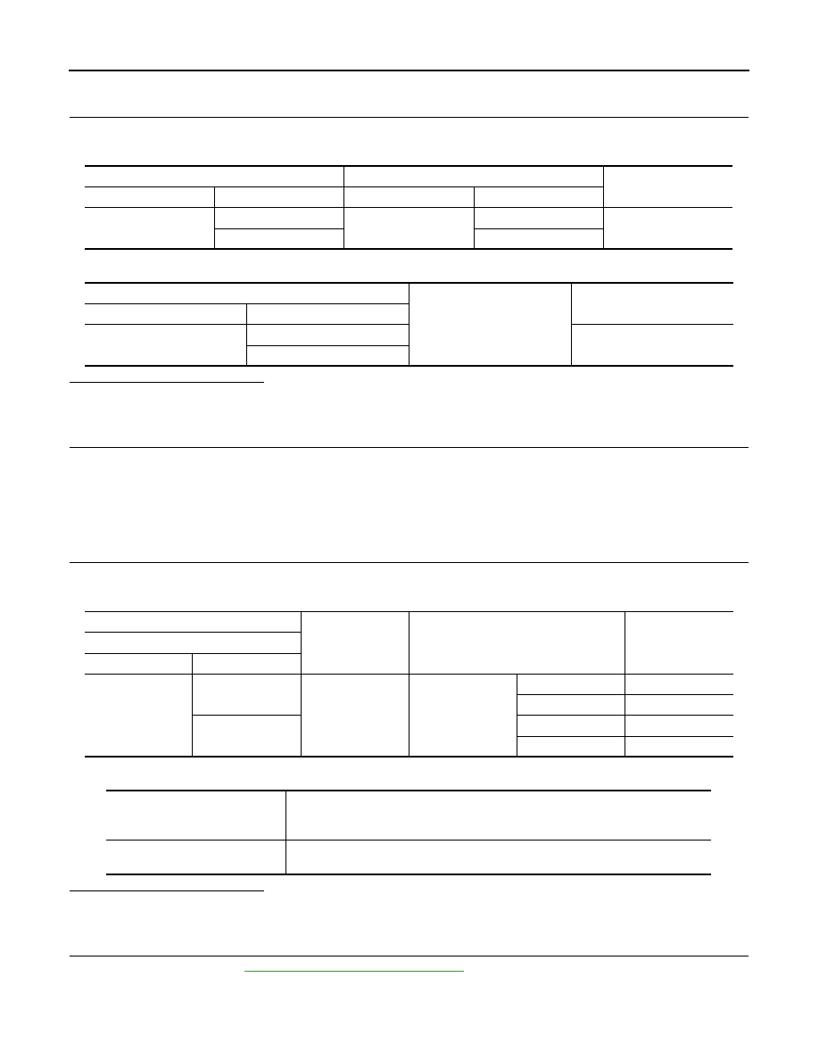
Check continuity between IPDM E/R harness connector and steering lock unit harness connector.
3.
Check continuity between IPDM E/R harness connector and ground.
Is the inspection result normal?
YES
>> GO TO 3.
NO
>> Repair or replace harness.
3.
REPLACE STEERING LOCK UNIT
1.
Replace steering lock unit.
2.
Perform the service procedure for steering lock unit replacement. Refer to CONSULT-III Operation Man-
ual NATS-IVIS/NVIS.
>> INSPECTION END
4.
CHECK BCM INPUT SIGNAL
1.
Turn ignition switch OFF.
2.
Check voltage between BCM harness connector and ground.
NOTE:
Is the inspection result normal?
YES
>> GO TO 5.
NO
>> GO TO 6.
5.
REPLACE BCM
1.
Replace BCM. Refer to
BCS-81, "Removal and Installation"
.
2.
Perform initialization of BCM and registration of all Intelligent Keys using CONSULT-III.
For initialization and registration procedures, refer to CONSULT-III Operation Manual NATS-IVIS/NVIS.
IPDM E/R
Steering lock unit
Continuity
Connector
Terminal
Connector
Terminal
E17
63
M12
8
Existed
65
3
IPDM E/R
Ground
Continuity
Connector
Terminal
E17
63
Not existed
65
(+)
(–)
Condition
Voltage (V)
(Approx.)
BCM
Connector
Terminal
M71
107
Ground
Steering lock unit
Lock
0
Unlock
12
108
Lock
12
Unlock
0
To lock the steering
1.
Set the selector lever in the P position.
2.
Turn the power supply position to the OFF position.
3.
Press any door switch.
To unlock the steering
1.
Set the selector lever in the P position.
2.
Press the push-button ignition switch with brake pedal not depressed.