Infiniti QX56 (Z62). Manual - part 1052


  Index      Infiniti     Infiniti QX56 (Z62) - service repair manual 2011 year


Search            


Content   ..  1050  1051  1052  1053   ..


Infiniti QX56 (Z62). Manual - part 1052


REAR WHEEL HUB AND HOUSING

RAX-9

< REMOVAL AND INSTALLATION >

C

E

F

G

H

I

J

K

L

M

A

B

RAX

N

O

P

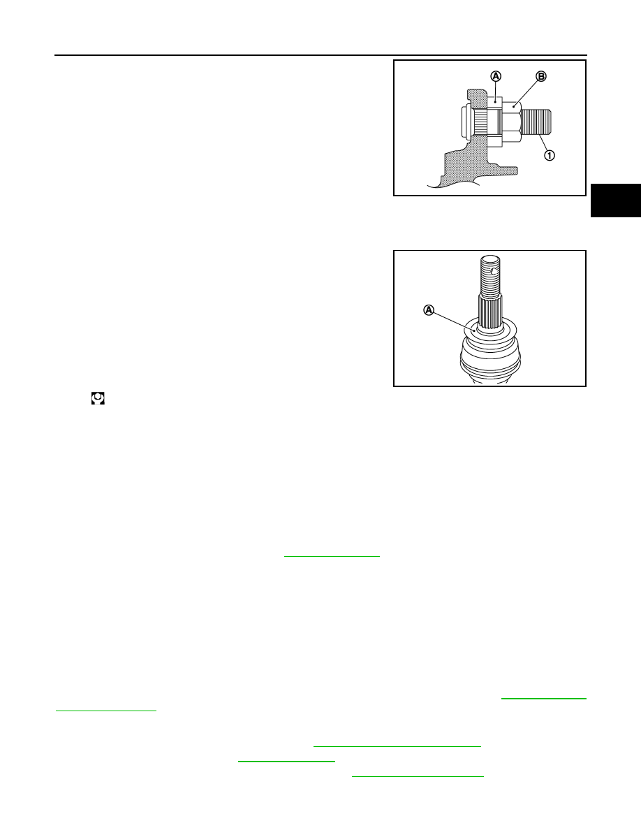
• Place a suitable washer (A) as shown in the figure to install the hub

bolts (1) by using the tightening force of the nut (B).

CAUTION:

• Check that there is no clearance between wheel hub and

bearing assembly, and hub bolt. 

• Never reuse hub bolt.

• Clean the matching surface of wheel hub lock nut and wheel hub and bearing assembly.

CAUTION:

Never apply lubricating oil to these matching surface.

• Clean the matching surface of drive shaft and wheel hub and bear-

ing assembly. And then apply paste [service parts (440037S000)]
to surface (A) of joint sub-assembly of drive shaft.

CAUTION:

Apply paste to cover entire flat surface of joint sub-assembly
of drive shaft.

• Use the following torque range for tightening the wheel hub lock

nut.

CAUTION:

• Since the drive shaft is assembled by press-fitting, use the tightening torque range for the wheel

hub lock nut.

• Be sure to use torque wrench to tighten the wheel hub lock nut. Never use a power tool.
NOTE:
Wheel hub lock nut tightening torque does not over torque for avoiding axle noise, and does not less than
torque for avoiding looseness.

• Perform the final tightening of each of parts under unladen conditions, which were removed when removing

wheel hub and bearing assembly and axle housing. 

• When installing the adjusting cap, check that there must be no play.
• Never reuse cotter pin, wheel hub lock nut, and bushing.
• Perform inspection after installation. Refer to 

RAX-9, "Inspection"

.

Inspection

INFOID:0000000006225467

INSPECTION AFTER REMOVAL

Wheel Hub and Bearing Assembly

Check the wheel hub and bearing assembly for wear, cracks, and damage. Replace if necessary.

Axle Housing

Check the axle housing for wear, cracks, and damage. Replace if necessary.

Ball Joint Inspection

Check for boot breakage, axial looseness, and torque of suspension arm ball joint. Refer to 

RSU-13, "Inspec-

tion and Adjustment"

.

INSPECTION AFTER INSTALLATION

1.

Adjust parking brake operation (stroke). Refer to 

PB-3, "Inspection and Adjustment"

.

2.

Check wheel alignment. Refer to 

RSU-6, "Inspection"

.

3.

Adjust neutral position of steering angle sensor. Refer to 

BRC-64, "Work Procedure"

.

JPDIF0300ZZ

Amount paste

1.0 – 3.0 g (0.04 – 0.10 oz)

: 218 – 223 N·m (22.3 – 22.7 kg-m, 161 – 164 ft-lb)

JPDIG0122ZZ

RAX-10

< REMOVAL AND INSTALLATION >

REAR WHEEL HUB AND HOUSING

4.

Adjust levelizer adjustment of height sensor. Refer to 

EXL-61, "LEVELIZER ADJUSTMENT : Special

Repair Requirement"

.

5.

Check standard vehicle height setting of vehicle height sensor. Refer to 

SCS-67, "Work Procedure"

.

REAR DRIVE SHAFT

RAX-11

< REMOVAL AND INSTALLATION >

C

E

F

G

H

I

J

K

L

M

A

B

RAX

N

O

P

REAR DRIVE SHAFT

Exploded View

INFOID:0000000006225468

Removal and Installation

INFOID:0000000006225469

REMOVAL

1.

Remove tire.

2.

Remove parking brake cable from suspension member. Refer to 

PB-5, "Removal and Installation"

.

3.

Remove wheel sensor harness. Refer to 

BRC-135, "REAR WHEEL SENSOR : Removal and Installation"

.

4.

Remove height sensor from rear lower link (right side). Refer to 

EXL-136, "Removal and Installation"

.

5.

Remove vehicle height sensor from rear lower link (left side). Refer to 

SCS-98, "Removal and Installa-

tion"

.

6.

Set suitable jack under rear lower link.

7.

Remove rear lower link (axle housing side). Refer to 

RSU-8, "Removal and Installation"

.

8.

Remove coil spring. Refer to 

RSU-8, "Removal and Installation"

.

9.

Remove cotter pin and adjusting cap, then loosen wheel hub lock nut. Refer to 

RAX-7, "Removal and

Installation"

.

1.

Housing

2.

Snap ring

3.

Ball cage/steel ball/inner race as-
sembly

4.

Stopper ring

5.

Boot band

6.

Boot

7.

Shaft

8.

Circular clip

9.

Joint sub-assembly

10. Dust shield

: Wheel side

1: NISSAN genuine grease or an equivalent.

2: Apply paste [service parts (440037S000)].

Refer to 

GI-4, "Components"

 for symbols not described on the above.

JPDIG0164GB

RAX-12

< REMOVAL AND INSTALLATION >

REAR DRIVE SHAFT

10. Put matching mark (A) on drive shaft and wheel hub and bearing

assembly.

CAUTION:

Use paint or similar substance for matching marks. Never
scratch the surface.

11. Patch wheel hub lock nut with a piece of wood. Hammer the

wood to disengage wheel hub and bearing assembly from drive
shaft.

CAUTION:

• Never place drive shaft joint at an extreme angle. Also be

careful not to overextend slide joint.

• Never allow drive shaft to hang down without support for

counterpart such as joint sub-assembly, and other parts.

NOTE:
Use a suitable puller if wheel hub and bearing assembly and drive shaft cannot be separated even after
performing the above procedure.

12. Remove wheel hub lock nut.

13. Remove mounting bolts between side flange and drive shaft.
14. Remove drive shaft from the vehicle.

15. Perform inspection after removal. Refer to 

RAX-16, "Inspection"

.

INSTALLATION

Note the following, and install in the reverse order of removal.
• Clean the matching surface of wheel hub lock nut and wheel hub and bearing assembly.

CAUTION:

Never apply lubricating oil to these matching surface.

• Clean the matching surface of drive shaft and wheel hub and bear-

ing assembly. And then apply paste [service parts (440037S000)]
to surface (A) of joint sub-assembly of drive shaft.

CAUTION:

Apply paste to cover entire flat surface of joint sub-assembly
of drive shaft.

• Use the following torque range for tightening the wheel hub lock

nut.

CAUTION:

• Since the drive shaft is assembled by press-fitting, use the tightening torque range for the wheel

hub lock nut.

• Be sure to use torque wrench to tighten the wheel hub lock nut. Never use a power tool.
NOTE:
Wheel hub lock nut tightening torque does not over torque for avoiding axle noise, and does not less than
torque for avoiding looseness.

• Perform the final tightening of each of parts under unladen conditions, which were removed when removing

wheel hub and bearing assembly and axle housing. 

• When installing the adjusting cap, check that there must be no play.
• Never reuse cotter pin, wheel hub lock nut.

WHEEL SIDE

WHEEL SIDE : Disassembly and Assembly

INFOID:0000000006225470

DISASSEMBLY

1.

Fix shaft with a vise.

CAUTION:

Protect shaft when fixing with a vise using aluminum or copper plates.

JPDIG0121ZZ

Amount paste

1.0 – 3.0 g (0.04 – 0.10 oz)

: 218 – 223 N·m (22.3 – 22.7 kg-m, 161 – 164 ft-lb)

JPDIG0122ZZ


Content   ..  1050  1051  1052  1053   ..