Infiniti QX56 (Z62). Manual - part 87
AV-202
< SYMPTOM DIAGNOSIS >
MULTI AV SYSTEM SYMPTOMS
RELATED TO RGB IMAGE
RELATED TO VOICE CONTROL
RELATED TO AUDIO
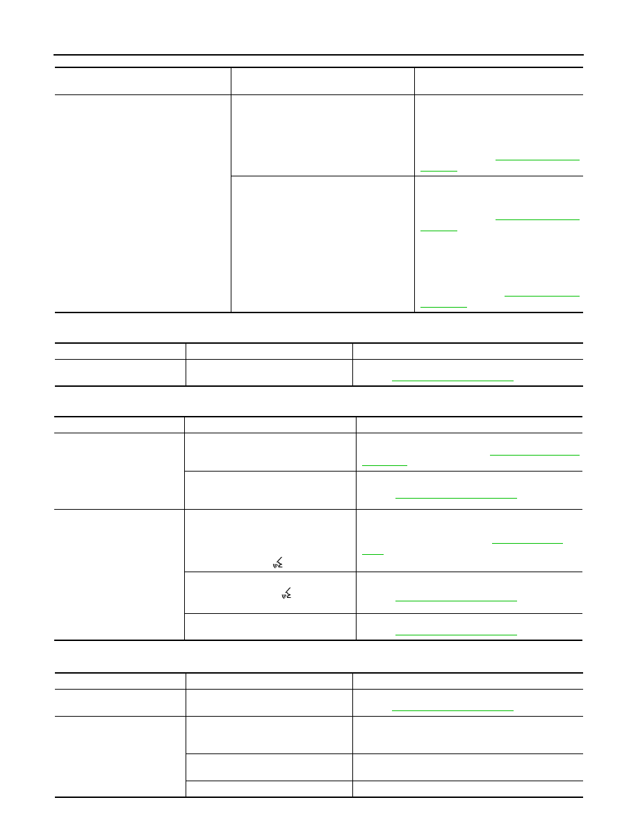
Symptoms
Check items
Probable malfunction location / Action to
take
The malfunction is detected in the sonar in-
dicator
(Always displayed in red)
The malfunction is detected in only 1 indica-
tor (Always displayed in red).
• Corner sensor malfunction in corre-
sponding area.
• Corner sensor harness circuit in corre-
sponding area.
Perform CONSULT-III “self-diagnosis” of
“SONAR”. Refer to
The malfunction is detected in all 4 indicators
(Always displayed in red).
• Corner sensor ground circuit malfunc-
tion.
Perform CONSULT-III “self-diagnosis” of
“SONAR”. Refer to
• Sonar control unit power supply and
ground circuits malfunction.
• AV communication circuits malfunc-
tion.
Perform CONSULT-III “self-diagnosis” of
“MULTI AV”. Refer to
.
Symptoms
Check items
Probable malfunction location
RGB image is not shown.
—
RGB digital image signal circuit malfunction.
Refer to
.
Symptoms
Check items
Probable malfunction location
The voice cannot be controlled
even if the voice control screen
is displayed.
Voice sounds at “Voice Microphone Test”
of Confirmation/Adjustment mode.
AV control unit malfunction.
Replace AV control unit. Refer to
Voice does not sound at “Voice Micro-
phone Test” of Confirmation/Adjustment
mode.
Microphone circuit malfunction.
Refer to
.
The voice cannot be controlled
(Voice control screen is not dis-
played).
• Hands-free phone system can be oper-
ated.
• Steering switch's “SOURCE”, “MENU
UP”, “MENU DOWN” and “ENTER”
switch works, but “
” it does not work.
Steering switch malfunction.
Replace steering wheel. Refer to
.
Steering switch's “SOURCE”, “MENU
UP”, “MENU DOWN”, “
” and “ENTER”
switches do not work.
Steering switch signal A circuit malfunction.
Refer to
.
None of the steering switch operations
work.
Steering switch ground circuit malfunction.
Refer to
.
Symptoms
Check items
Probable malfunction location
The disk cannot be removed.
—
Disk eject signal circuit malfunction.
Refer to
.
Audio sound is not heard.
No sound from all speakers.
• Amp. ON signal circuit malfunction.
• BOSE amp. power supply and ground circuits malfunc-
tion.
Sound is not heard from woofer.
• Woofer power supply and ground circuit malfunction.
• Sound signal (woofer) circuit malfunction.
Sound is heard only from specific places.
Sound signals circuit of suspect system.