Infiniti QX56 (Z62). Manual - part 65


  Index      Infiniti     Infiniti QX56 (Z62) - service repair manual 2011 year


Search            


Content   ..  63  64  65  66   ..


Infiniti QX56 (Z62). Manual - part 65


AV-114

< BASIC INSPECTION >

CALIBRATING CAMERA IMAGE (AROUND VIEW MONITOR)

3.

Select “Camera Cont.” of Confirmation/ Adjustment mode, and then set to “Fine Tuning of Birds-Eye View”
mode.

4.

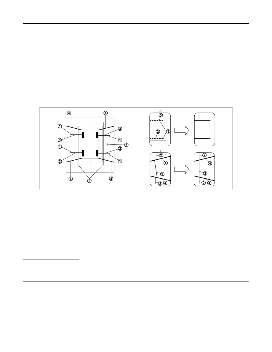
Select left and right cameras by pressing the “CAMERA” switch, and perform the following confirmation. 

-

Check that target line 1 is aligned with the marker on the screen. Overlap the line aligned to the marker
with the upper/lower switches if necessary. 

-

Check if there is a difference between target lines 2 between cameras. Adjust target lines 2 to be straight
lines by operating the center dial and left/right switches if necessary. 

CAUTION:

Never adjust the front camera and rear camera. Only adjust the right and left cameras. 

Operate the center dial slowly because the changing of the screen takes approximately 1 sec-
ond. 

Simplified target line adjustment method

5.

Adjust left and right cameras. Check that the difference between target line 1 and the marker on the
screen, and between target lines 2 is solved. 
NOTE:
• It can be initialized to the NISSAN factory default condition with “Initialize Camera Image Calibration” of

“Calibrating Camera Image”. 

• The adjustment value is cancelled on this mode by performing “Initialize Camera Image Calibration”. 

Is the difference corrected?

YES

>> Finish the writing to around view monitor control unit by pressing “ENTER” switch. 

NO

>> GO TO 5.

5.

PERFORM “CALIBRATING CAMERA IMAGE”

Preparation of target line
1.

Hang a string with a weight as shown in the figure. Put the points FM0, RM0 (mark) on the ground at the
center of the vehicle front end and rear end with white packing tape or a pen. 

2.

Route the vinyl string under the vehicle, and then pull and fix it on the point approximately 1.0 m (39.9 in)
to the front and rear of the vehicle through the points FM0 and RM0 using packing tape. 

1.

Target lines 1

2.

Target lines 2

A.

Approx. 30 cm (11.8 in)

B.

Approx. 1.0 m (39.3 in)

JSNIA0929ZZ

1.

Target lines 1

2.

Target lines 2

3.

Marker for target line 1

4.

Boundary between cameras

5.

Crosshairs cursor (mark indicated 
the selected camera)

A.

Adjustment method for target lines 1 
(right)

B.

Adjustment method for target lines 2 
(right)

AV

CALIBRATING CAMERA IMAGE (AROUND VIEW MONITOR)

AV-115

< BASIC INSPECTION >

C

D

E

F

G

H

I

J

K

L

M

B

A

O

P

Target line preparation procedure 1

3.

Put the points FM and RM (mark) 75 cm (29.5 in) from the points FM0 and RM0 individually. 

4.

Route the vinyl string through the points FM and RM using a triangle scale, and then fix it at approximately
1.5 m (59 in) on both sides with packing tape. 

5.

Put the points FL, FR, RL, and RR (mark) to both right and left [vehicle width / 2 + 30 cm (11.8 in)] from the
points FM and RM. 

Target line preparation procedure 2

6.

Draw the lines of the points FL – RL and FR – RR with vinyl string, and fix it with packing tape. 

7.

Put a mark on the center of each axle, draw vertical lines to the lines of the points FL – RL and FR – RR
from the marks on the center of the axle using a triangle scale, and then fix the lines using packing tape. 

JSNIA3128ZZ

1.

Thread

2.

Weight

3.

Point FM0 (mark)

4.

Point RM0 (mark)

5.

Packing tape (to fix the vinyl string)

6.

Vinyl string

JSNIA0921ZZ

1.

Point FM

2.

Point RM

3.

Triangle scale

4.

Point FL (mark)

5.

Point FR (mark)

6.

Point RL (mark)

7.

Point RR (mark)

A.

75 cm (29.5 in)

B.

Approx. 1.5 m (59 in)

C.

30 cm (11.8 in)
[Vehicle width/ 2 + 30 cm (11.8 in) 
from the points FM and RM]

AV-116

< BASIC INSPECTION >

CALIBRATING CAMERA IMAGE (AROUND VIEW MONITOR)

Target line preparation procedure 3

Perform “Calibrating Camera Image”
1.

Select “Camera Cont.” of “Confirmation/ Adjustment” mode, and then set to “Calibrating Camera Image”
mode. 

2.

Overlap the target lines drawn on the ground with the calibration
marker on the screen by operating the center dial and upper/
lower/left/right switches of multifunction switch on each screen
of “Rear Camera”, “Pass-Side Camera”, “Front Camera”, “Dr-
Side Camera”. 

3.

“Writing...” is displayed by pressing the “ENTER” switch, and then the adjustment result is written to the
around view monitor control unit. 

CAUTION:

Check that “Writing...” is displayed. Do never perform other operations while “Writing...” is dis-
played. 

>> GO TO 6.

6.

PERFORM “FINE TUNING OF BIRDS-EYE VIEW”

This mode is designed to align the boundary between each camera image that could not be aligned in the
“Calibrating Camera Image” mode. 
1.

Select “Camera Cont.” of “Confirmation/ Adjustment” mode, and then set to “Fine Tuning of Birds-Eye
View” mode. 

2.

Operate the center dial and upper/lower/left/right switch to over-
lap the marker on the screen and the target lines on the ground. 
NOTE:
Move the “+”- mark on the camera position to adjustment by
pressing the “CAMERA” switch. 

3.

When the target line is overlapped on the marker, press the
“ENTER” switch to write the adjustment result to the around
view monitor control unit. 

CAUTION:

Check that “Writing...” is displayed. Do never perform other
operations while “Writing...” is displayed. 
NOTE:

JSNIA0922ZZ

1.

Point FL

2.

Point FR

3.

Point RL

4.

Point RR

5.

Center position of axle

6.

Triangle scale

Adjustment range

Rotation direction (Center dial)

: 31 patterns (16 on the center)

Upper/lower direction (upper/lower 
switch)

99 – 99

Left/right direction (left/right switch)

99 – 99

JSNIA2379ZZ

JSNIA2280ZZ

AV

CALIBRATING CAMERA IMAGE (AROUND VIEW MONITOR)

AV-117

< BASIC INSPECTION >

C

D

E

F

G

H

I

J

K

L

M

B

A

O

P

• It can be initialized to the NISSAN factory default condition with “Initialize Camera Image Calibration” of

“Calibrating Camera Image”. 

• The adjustment value is cancelled on this mode by performing “Initialize Camera Image Calibration”. 

>> Calibration end


Content   ..  63  64  65  66   ..