Infiniti QX4 (R50). Manual - part 24
 

  Index      Infiniti     Infiniti QX4 (R50) - service repair manual 2001 year


Search            copyright infringement  


Content   ..  22  23  24  25   ..


Infiniti QX4 (R50). Manual - part 24


Terminal

No.

Wire color

Item

Condition

Judgement

standard

(Approx.)

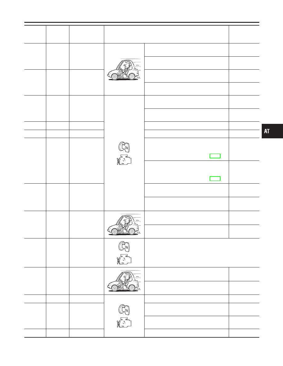
11

L/W

Shift solenoid
valve A

When shift solenoid valve A operates.
(When driving in “D

1

” or “D

4

”.)

Battery volt-
age

When shift solenoid valve A does not operate.
(When driving in “D

2

” or “D

3

”.)

0V

12

L/R

Shift solenoid
valve B

When shift solenoid valve B operates.
(When driving in “D

1

” or “D

2

”.)

Battery volt-
age

When shift solenoid valve B does not operate.
(When driving in “D

3

” or “D

4

”.)

0V

13

GY

O/D OFF indica-
tor lamp

When setting overdrive control switch in “ON”
position.

Battery volt-
age

When setting overdrive control switch in
“OFF” position.

0V

14

—

—

—

—

15

—

—

—

—

16

OR/W

Closed throttle
position switch
(in throttle posi-
tion switch)

When releasing accelerator pedal after warm-
ing up engine.
Refer to “Preparation”, “TCM SELF-DIAG-
NOSTIC PROCEDURE (No Tools)”, AT-46.

Battery volt-
age

When depressing accelerator pedal after
warming up engine.
Refer to “Preparation”, “TCM SELF-DIAG-
NOSTIC PROCEDURE (No Tools)”, AT-46.

0V

17

OR/B

Wide open
throttle position
switch
(in throttle posi-
tion switch)

When depressing accelerator pedal more than
half-way after warming up engine.

Battery volt-
age

When releasing accelerator pedal after warm-
ing up engine.

0V

18

B/Y

ASCD cruise sig-
nal

When ASCD cruise is being performed.
(“CRUISE” light comes on.)

Battery volt-
age

When ASCD cruise is not being performed.
(“CRUISE” light does not comes on.)

0V

19

W/R

Power source

Same as No. 10

20

L/B

Overrun clutch
solenoid valve

When overrun clutch solenoid valve operates.

Battery volt-
age

When overrun clutch solenoid valve does not
operate.

0V

21

—

—

—

—

22

GY

Overdrive control
switch

When setting overdrive control switch in “ON”
position

Battery volt-
age

When setting overdrive control switch in
“OFF” position

0V

23

—

—

—

—

GI

MA

EM

LC

EC

FE

TF

PD

AX

SU

BR

ST

RS

BT

HA

SC

EL

IDX

TROUBLE DIAGNOSIS — GENERAL DESCRIPTION

TCM Terminals and Reference Value (Cont’d)

AT-93

Terminal

No.

Wire color

Item

Condition

Judgement

standard

(Approx.)

24

W/G

ASCD OD cut
signal

When “ACCEL” set switch on ASCD cruise is
released.

5 - 10V

When “ACCEL” set switch on ASCD cruise is
applied.

Less than 2V

25

B

Ground

—

0V

26

G

PNP switch “1”
position

When setting selector lever to “1” position.

Battery volt-
age

When setting selector lever to other positions.

0V

27

G/W

PNP switch “2”
position

When setting selector lever to “2” position.

Battery volt-
age

When setting selector lever to other positions.

0V

28

R/Y

Power source
(Memory back-up)

or

When turning ignition switch to “OFF”.

Battery volt-
age

When turning ignition switch to “ON”.

Battery volt-
age

29

W

Revolution sensor
(Measure in AC
range)

When vehicle cruises at 30 km/h (19 MPH).

1V or more
Voltage rises
gradually in
response to
vehicle speed.

When vehicle parks.

0V

30*2

W

(RX)

—

—

31*2

L

(TX)

—

—

32

P/B

Throttle position
sensor
(Power source)

Ignition switch “ON”.

4.5 - 5.5V

Ignition switch “OFF”.

0V

33*1

G/R

LAN

—

—

34

L

PNP switch “D”
position

When setting selector lever to “D” position.

Battery volt-
age

When setting selector lever to other positions.

0V

35

Y

PNP switch “R”
position

When setting selector lever to “R” position.

Battery volt-
age

When setting selector lever to other positions.

0V

36

P

PNP switch “N” or
“P” position

When setting selector lever to “N” or “P” posi-
tion.

Battery volt-
age

When setting selector lever to other positions.

0V

37

—

—

—

—

38

W

Turbine revolution
sensor (Measure
in AC range)

When engine is running at 1,000 rpm

1.2V
Voltage rises
gradually in
response to
engine speed.

TROUBLE DIAGNOSIS — GENERAL DESCRIPTION

TCM Terminals and Reference Value (Cont’d)

AT-94

Terminal

No.

Wire color

Item

Condition

Judgement

standard

(Approx.)

39

W/B

Engine speed
signal

Refer to EC-127, “ECM INSPECTION
TABLE”.

—

40

W/L

Vehicle speed
sensor

When moving vehicle at 2 to 3 km/h (1 to 2
MPH) for 1 m (3 ft) or more.

Voltage varies
between less
than 1.0V and
more than
4.5V.

41

P

Throttle position
sensor

When depressing accelerator pedal slowly
after warming up engine.
(Voltage rises gradually in response to throttle
position.)

Fully-closed
throttle:
0.5V - 0.7V
Fully-open
throttle:
4V

42

B

Throttle position
sensor
(Ground)

—

0V

45

G/Y

Stop lamp switch

When depressing brake pedal

Battery volt-
age

When releasing brake pedal

0V

46

W

Transfer control
unit

—

—

47

R

A/T fluid tempera-
ture sensor

When ATF temperature is 20°C (68°F).

1.5V

When ATF temperature is 80°C (176°F).

0.5V

48

B

Ground

—

0V

*1: These terminals are connected to the ECM.
*2: These terminals are connected to the Data link connector for CONSULT-II.

GI

MA

EM

LC

EC

FE

TF

PD

AX

SU

BR

ST

RS

BT

HA

SC

EL

IDX

TROUBLE DIAGNOSIS — GENERAL DESCRIPTION

TCM Terminals and Reference Value (Cont’d)

AT-95

Wiring Diagram — AT — MAIN

NBAT0185

MAT907A

TROUBLE DIAGNOSIS FOR POWER SUPPLY

Wiring Diagram — AT — MAIN

AT-96


Content   ..  22  23  24  25   ..