Infiniti Q45. Manual - part 905
TROUBLE DIAGNOSIS FOR SYSTEM
WT-29
C
D
F
G
H
I
J
K
L
M
A
B
WT
TROUBLE DIAGNOSIS FOR SYSTEM
PFP:00000
Power Supply Circuit
NES000D7
LOW TIRE PRESSURE WARNING CONTROL UNIT TERMINALS AND REFERENCE VALUE
Data are reference value and are measured between each terminal and ground.
CAUTION:
When using a circuit tester to measure voltage for inspection, be sure not to extend forcibly any connector terminals.
DIAGNOSTIC PROCEDURE
1.
CHECK POWER SUPPLY
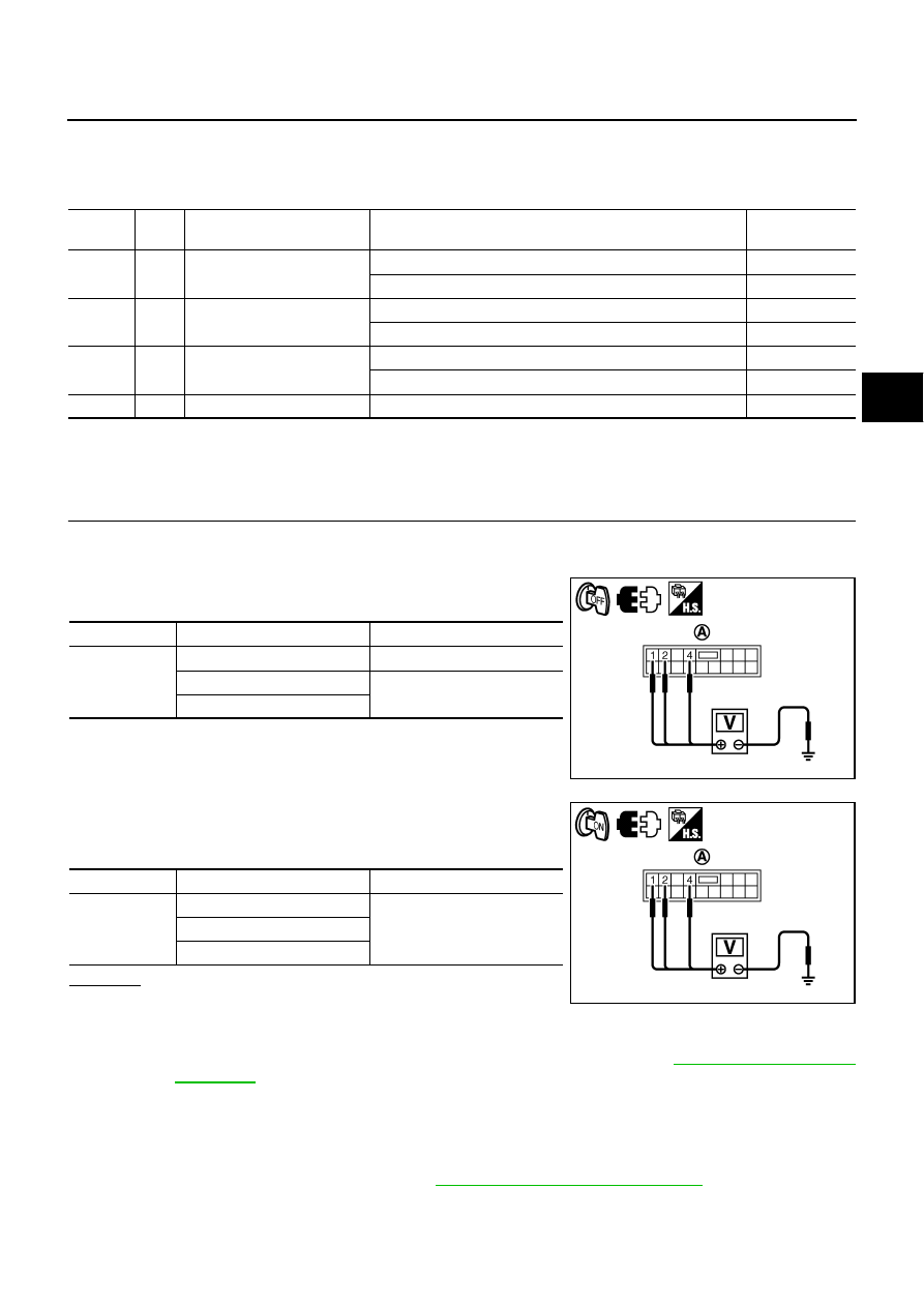
1.
Turn ignition switch “OFF”.
2.
Disconnect low tire pressure warning control unit harness connector.
3.
Check voltage between low tire pressure warning control unit
harness connector (A) terminals and ground.
4.
Turn ignition switch “ON”. (Do not start engine.)
5.
Check voltage between low tire pressure warning control unit
harness connector (A) terminals and ground.
OK or NG
OK
>> GO TO 2.
NG
>> Check the following. If any items are damaged, repair or
replace damaged parts.
●
10A fuses [No. 1, 6, 21 located in the fuse block (J/B) No.1]. Refer to
●
Harness for short or open between battery and low tire pressure warning control unit harness
connector M84 terminal 1.
●
Harness for short or open between ignition switch and low tire pressure warning control unit
harness connector M84 terminals 2 and 4.
●
Battery and ignition switch. Refer to
.
Terminal
Wire
color
Item
Condition
Data (Approx.)
1
Y/G
Power supply
(Memory back-up)
Ignition switch: ON
Battery voltage
Ignition switch: OFF
Battery voltage
2
BR/W
Power supply
Ignition switch: ON
Battery voltage
Ignition switch: OFF
0 V
4
L/OR
Power supply
Ignition switch: ACC
Battery voltage
Ignition switch: OFF
0 V
11
B
Ground
Always
0 V
Connector
Terminal
Voltage (Approx.)
M84
1 - Ground
Battery voltage
2 - Ground
0 V
4 - Ground
SEIA0746E
Connector
Terminal
Voltage (Approx.)
M84
1 - Ground
Battery voltage
2 - Ground
4 - Ground
SEIA0747E