Infiniti Q45. Manual - part 855


  Index      Infiniti     Infiniti Q45 - service repair manual 2006 year


Search            copyright infringement  


Content   ..  853  854  855  856   ..


Infiniti Q45. Manual - part 855


CLIMATE CONTROLLED SEAT

SE-175

C

D

E

F

G

H

J

K

L

M

A

B

SE

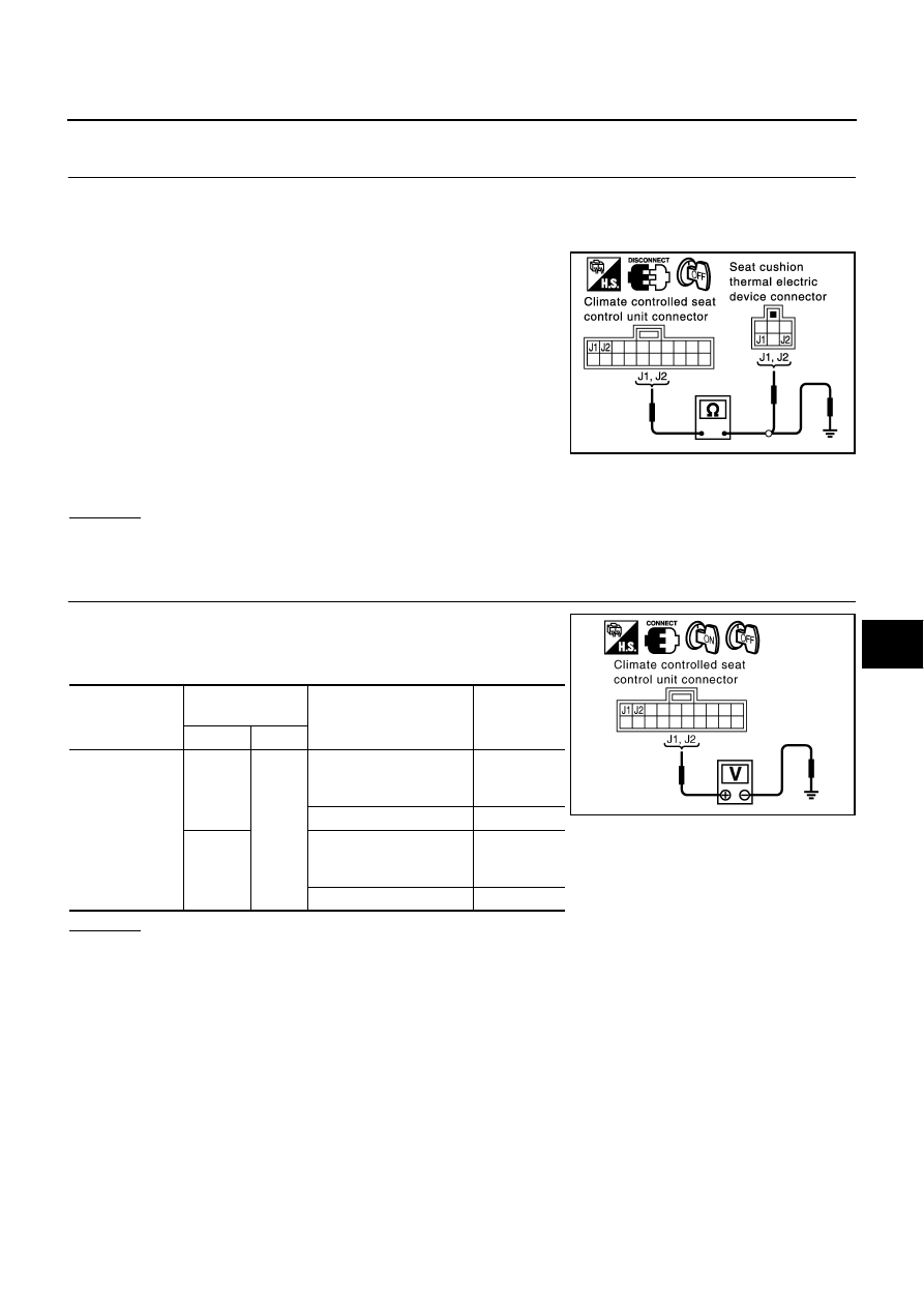
Check Seat Cushion Thermal Electric Device Circuit

NIS0015B

1. 

CHECK SEAT CUSHION THERMAL ELECTRIC DEVICE HARNESS

1.

Turn ignition switch OFF.

2.

Disconnect climate controlled seat control unit connector and seat cushion thermal electric device con-
nector.

3.

Check continuity between climate controlled seat control unit
connector B159 (driver side), B359 (passenger side) terminal
J1, J2 and climate controlled seat temperature dial connector
B154 (driver side), B354 (passenger side) terminal J1, J2.

4.

Check continuity between climate controlled seat control unit
connector B159 (driver side), B359 (passenger side) terminal
J1, J2 and ground.

OK or NG

OK

>> GO TO 2.

NG

>> Repair or replace harness.

2. 

CHECK SEAT CUSHION THERMAL ELECTRIC DEVICE POWER SUPPLY CIRCUIT

1.

Connect climate controlled seat control unit connector.

2.

Check voltage between climate controlled seat control unit con-
nector and ground.

OK or NG

OK

>> Seat cushion Thelma electric device circuit check is OK.

NG

>> Replace seat cushion thermal electric device.

J1 (Y/G) 

 J1 (Y/G)

: Continuity should exist

J2 (W/L) 

 J2 (W/L)

: Continuity should exist

J1 (Y/G) 

 Ground

: Continuity should not exist

J2 (W/L) 

 Ground

: Continuity should not exist

PIIA3339E

Connector

Terminal

(Wire color)

Condition

Voltage (V)

(Approx)

(+)

(–)

B159

(Driver side)

B359

(Passenger side)

J1 (Y/G)

Ground

Turn ignition switch ON,
climate controlled seat 
switch turn “HEAT”

 0 – Battery 

voltage

Turn ignition switch OFF

0

J2 (WL)

Turn ignition switch ON,
climate controlled seat 
switch turn “COOL”

 0 – Battery 

voltage

Turn ignition switch OFF

0

PIIB2126E

SE-176

CLIMATE CONTROLLED SEAT

Check Seat Cushion Thermal Electric Device Sensor Circuit

NIS0015C

1. 

CHECK SEAT CUSHION THERMAL ELECTRIC DEVICE HARNESS

1.

Turn ignition switch OFF.

2.

Disconnect climate controlled seat control unit connector and seat cushion thermal electric device con-
nector.

3.

Check continuity between climate controlled seat control unit
connector B159 (driver side), B359 (passenger side) terminal
J17, J18 and climate controlled seat temperature dial connector
B154 (driver side), B354 (passenger side) terminal J17, J18.

4.

Check continuity between climate controlled seat control unit
connector B159 (driver side), B359 (passenger side) terminal
J17, J18 and ground.

OK or NG

OK

>> GO TO 2.

NG

>> Repair or replace harness.

2. 

CHECK SEAT CUSHION THERMAL ELECTRIC DEVICE SENSOR

1.

Connect climate controlled seat control unit connector and seat cushion thermal electric device connector.

2.

Turn ignition switch ON.

3.

Check voltage between seat cushion thermal electric device
connector B154 (driver side), B354 (passenger side) terminal
J18 and body ground.

OK or NG

OK

>> Seat cushion thermal electric device sensor circuit

inspection is OK.

NG

>> Replace seat cushion thermal electric device.

J17 (B/R) 

 J17 (B/R)

: Continuity should exist

J18 (G/R) 

 J18 (G/R)

: Continuity should exist

J17 (B/R) 

 Ground

: Continuity should not exist

J18 (G/R) 

 Ground

: Continuity should not exist

PIIA3337E

J18 (G/R) 

 Ground

: 0.5V 

 4V (Approx.)

PIIA3336E

CLIMATE CONTROLLED SEAT

SE-177

C

D

E

F

G

H

J

K

L

M

A

B

SE

Check Seatback Thermal Electric Device Circuit

NIS0015D

1. 

CHECK SEATBACK THERMAL ELECTRIC DEVICE HARNESS

1.

Turn ignition switch OFF.

2.

Disconnect climate controlled seat control unit connector and seatback thermal electric device connector.

3.

Check continuity between climate controlled seat control unit
connector B159 (driver side), B359 (passenger side) terminal
J11, J12 and seatback thermal electric device connector B153
(driver side), B353 (passenger side) terminal J11, J12.

4.

Check continuity between climate controlled seat control unit
connector B159 (driver side), B359 (passenger side) terminal
J11, J12 and ground.

OK or NG

OK

>> GO TO 2.

NG

>> Repair or replace harness.

2. 

CHECK SEATBACK THERMAL ELECTRIC DEVICE POWER SUPPLY CIRCUIT

1.

Connect climate controlled seat control unit connector and seat-
back thermal electric device connector.

2.

Check voltage between climate controlled seat control unit con-
nector and ground.

OK or NG

OK

>> Seatback thermal electric device circuit check is OK.

NG

>> Replace seat cushion thermal electric device.

J11 (B/R) 

 J11 (B/R)

: Continuity should exist

J12 (PU/W) 

 J12 (PU/W)

: Continuity should exist

J11 (B/R) 

 Ground

: Continuity should not exist

J12 (PU/W) 

 Ground

: Continuity should not exist

PIIA3343E

Connector

Terminal

(Wire color)

Condition

Voltage (V)

(Approx)

(+)

(–)

B159

(Driver side)

B359

(Passenger side)

J11 (B/R)

Ground

Turn ignition switch ON,
climate controlled seat 
switch turn “HEAT

 0 – Battery 

voltage

Turn ignition switch OFF

0

J12

(PU/W)

Turn ignition switch ON,
climate controlled seat 
switch turn “COOL”

 0 – Battery 

voltage

Turn ignition switch OFF

0

PIIB2127E

SE-178

CLIMATE CONTROLLED SEAT

Check Seatback Thermal Electric Device Sensor Circuit 

NIS0015E

1. 

CHECK SEATBACK THERMAL ELECTRIC DEVICE HARNESS

1.

Turn ignition switch OFF.

2.

Disconnect climate controlled seat control unit connector and seatback thermal electric device connector.

3.

Check continuity between climate controlled seat control unit
connector B159 (driver side), B359 (passenger side) terminal
J19, J20 and seatback thermal electric device connector B153
(driver side), B353 (passenger side) terminal J19, J20.

4.

Check continuity between climate controlled seat control unit
connector B159 (driver side), B359 (passenger side) terminal
J19, J20 and ground.

OK or NG

OK

>> GO TO 2.

NG

>> Repair or replace harness.

2. 

CHECK SEAT CUSHION THERMAL ELECTRIC DEVICE SENSOR

1.

Connect climate controlled seat control unit connector and seatback thermal electric device connector.

2.

Turn ignition switch ON.

3.

Check voltage between seat cushion thermal electric device
connector B153 (driver side), B353 (passenger side) terminal
J19 and ground.

OK or NG

OK

>> Seatback thermal electric device sensor circuit inspec-

tion is OK.

NG

>> Replace seatback thermal electric device.

Check Blower Motor Power Supply Circuit 

NIS0015F

1. 

CHECK BLOWER MOTOR HARNESS

1.

Turn ignition switch OFF.

2.

Disconnect climate controlled seat control unit and blower motor connector.

3.

Check continuity between climate controlled seat control unit
connector B159 (driver side), B359 (passenger side) terminal
J10 and blower motor connector B155 (driver side), B355 (pas-
senger side) terminal J10.

4.

Check continuity between climate controlled seat control unit
connector B159 (driver side), B359 (passenger side) terminal
J10 and ground.

OK or NG

OK

>> GO TO 2.

NG

>> Repair or replace harness.

J19 (L/OR) 

 J19 (L/OR)

: Continuity should exist

J20 (R/L) 

 J20 (R/L)

: Continuity should exist

J19 (L/OR) 

 Ground

: Continuity should not exist

J20 (R/L) 

 Ground

: Continuity should not exist

PIIA3341E

J19 (L/OR) 

 Ground

: 0.5V 

 4V (Approx)

PIIA3340E

J10 (PU) 

 J10 (PU)

: Continuity should exist

J10 (PU) 

 Ground

: Continuity should not exist

PIIA3326E


Content   ..  853  854  855  856   ..