Infiniti Q45. Manual - part 828
AUTOMATIC DRIVE POSITIONER
SE-67
C
D
E
F
G
H
J
K
L
M
A
B
SE
Check Detention Switch Circuit
NIS00130
1.
CHECK FUNCTION
With CONSULT-II
Check that when the A/T selector lever is in P-position, "DETENT
SW" on the DATA MONITOR becomes ON.
Without CONSULT-II
Carry out "SWITCH MONITOR" in the self-diagnosis function, and operate the A/T selector lever to check.
Refer to
OK or NG
OK
>> System is OK.
NG
>> GO TO 2.
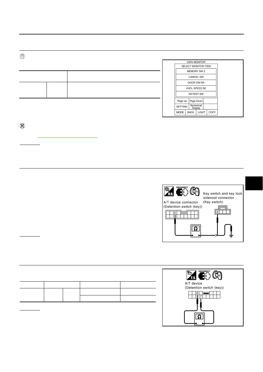
2.
CHECK DETENTION SWITCH POWER SUPPLY CIRCUIT HARNESS
1.
Turn ignition switch OFF.
2.
Disconnect A/T device (detention switch) connector and key switch and key lock solenoid connector.
3.
Check continuity harness between A/T device (detention switch)
connector M97 terminal 6 and key switch and key lock solenoid
connector M64 terminal 4.
4.
Check continuity harness between A/T device (detention switch)
connector M97 terminal 6 and ground.
OK or NG
OK
>> GO TO 3.
NG
>> Repair or replace harness between A/T device (deten-
tion switch) and key switch and key lock solenoid.
3.
CHECK DETENTION SWITCH
Check continuity between A/T device (detention switch) connector
M97 terminal 6 and 7.
OK or NG
OK
>> GO TO 4.
NG
>> Replace detention switch.
Monitor item
[OPERATION or UNIT]
Contents
DETENT SW
"ON/OFF"
The selector lever position "P position (ON)/other than
P position (OFF)" judged from the detente switch
signal is displayed.
PIIA0291E
6 (PU/W) – 4 (PU/W)
: Continuity should exist.
6 (PU/W) – Ground
:Continuity should not exist.
PIIB1743E
Connector
Terminals
Condition
Continuity
M97
6
7
P–position
No
Other than P–position
Yes
PIIB1744E