Infiniti Q45. Manual - part 825
AUTOMATIC DRIVE POSITIONER
SE-55
C
D
E
F
G
H
J
K
L
M
A
B
SE
4.
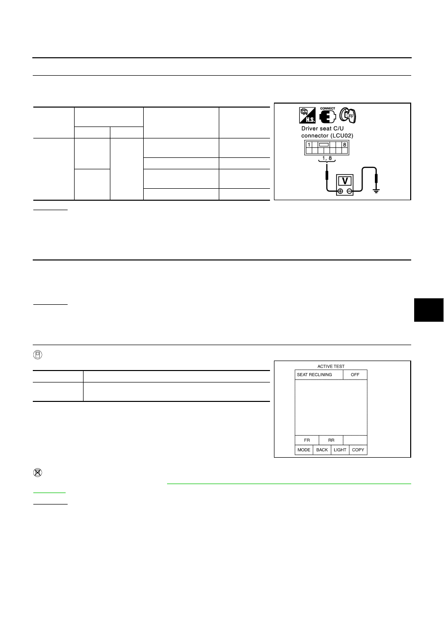
CHECK DRIVER SEAT CONTROL UNIT OUTPUT SIGNAL
1.
Connect the driver seat control unit connector and sliding motor connector.
2.
Check voltage between the driver seat control unit connector.
OK or NG
OK
>> Replace sliding motor.
NG
>> Replace driver seat control unit.
Check Reclining Motor Circuit
NIS0012R
1.
CHECK SEAT RECLINING MECHANISM
Check following.
●
Operation malfunction caused by an interference with the center pillar or center console
●
Operation malfunction and interference with other parts by poor installation
OK or NG
OK
>> GO TO 2.
NG
>> Repair the malfunction part and check again.
2.
CHECK FUNCTIONAL
With CONSULT-II
Check operation with "SEAT RECLINING" in ACTIVE TEST.
Without CONSULT-II
Perform the self-diagnosis. Refer to
SE-50, "ON BOARD DIAGNOSIS FOR AUTOMATIC DRIVE POSI-
.
OK or NG
OK
>> System is OK.
NG
>> GO TO 3.
Connector
Terminals
(Wire color)
Condition
Voltage (V)
(Approx.)
(+)
(–)
B142
1 (W)
Ground
Sliding switch
(forward operation)
Battery voltage
Sliding switch OFF
0
8 (BR)
Sliding switch
(backward operation)
Battery voltage
Sliding switch OFF
0
PIIA4895E
Test item
Description
SEAT
RECLINING
The reclining motor is activated by receiving the drive signal.
PIIA0268E