Infiniti Q45. Manual - part 795
CHARGING SYSTEM
SC-25
C
D
E
F
G
H
I
J
L
M
A
B
SC
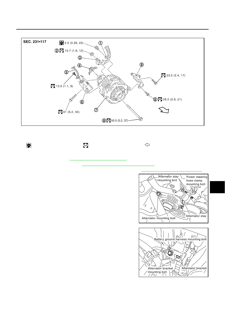
Removal and Installation
NKS0016W
REMOVAL
1.
Remove battery. Refer to
SC-8, "Removal and Installation"
.
2.
Remove air intake duct. Refer to
EM-17, "AIR CLEANER AND AIR DUCT"
3.
Remove alternator, water pump and A/C compressor belt. Refer to
EM-14, "Removal and Installation"
.
4.
Remove alternator mounting bolts.
5.
Remove power steering hose clamp mounting bolt.
6.
Remove alternator stay mounting bolts and alternator stay.
7.
Remove battery ground harness mounting bolt.
8.
Remove alternator bracket mounting bolts and alternator
bracket.
1.
Alternator ground harness
2.
“B” terminal nut
3.
“B” terminal harness
4.
Alternator nut
5.
Battery ground harness
6.
Alternator bracket
7.
Alternator
8.
Alternator mounting bolt
9.
Alternator stay
: N·m (kg-m, in-lb)
: N·m (kg-m, ft-lb)
: Engine front
SKIB6549E
PKIA2210E
PKIA2211E