Infiniti Q45. Manual - part 769
FRONT OIL SEAL
RFD-13
C
E
F
G
H
I
J
K
L
M
A
B
RFD
4.
Apply anti-corrosion oil to the thread and seat of new drive pin-
ion lock nut, and temporarily tighten drive pinion lock nut to drive
pinion.
CAUTION:
Do not reuse drive pinion lock nut.
5.
Tighten to drive pinion lock nut, while adjust total preload torque.
CAUTION:
●
Adjust to the lower limit of the drive pinion lock nut tight-
ening torque first.
●
If the preload torque exceeds the specified value, replace
collapsible spacer and tighten it again to adjust. Do not
loosen drive pinion lock nut to adjust the preload torque.
6.
Make a stamping for identification of front oil seal replacement
frequency. Refer to
RFD-10, "IDENTIFICATION STAMP OF REPLACEMENT FREQUENCY OF FRONT
CAUTION:
Be sure to make a stamping after replacing front oil seal.
7.
Install propeller shaft. Refer to
PR-5, "Removal and Installation"
8.
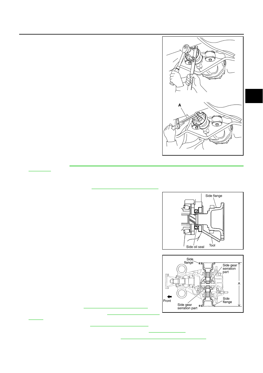
Install side flange with the following procedure.
a.
Attach the protector to side oil seal.
b.
After the side flange is inserted and the serrated part of side
gear has engaged the serrated part of flange, remove the pro-
tector.
c.
Put suitable drift on the center of side flange, then drive it until
sound changes.
NOTE:
When installation is completed, driving sound of the side flange
turns into a sound which seems to affect the whole final drive.
d.
Confirm that the dimension of the side flange installation (Mea-
surement A) in the figure comes into the following.
9.
Install drive shaft. Refer to
.
10. Install rear wheel sensor. Refer to
.
11. Install center muffler. Refer to
.
12. Refill gear oil to the final drive and check oil level. Refer to
.
13. Check the final drive for oil leakage. Refer to
RFD-9, "OIL LEAKAGE AND OIL LEVEL"
Tool number
A: ST3127S000 (J-25765-A)
Drive pinion lock nut tightening torque:
147 - 323 N·m (15 - 32 kg-m, 109 - 238 ft-lb)
Total preload torque:
Total preload torque should equal the measurement
taken during removal plus an additional 0.1 - 0.4 N·m
(0.01 - 0.04 kg-m, 1 - 3 in-lb).
Tool number
: KV38107900 (J-39352)
PDIA0981E
SDIA0822E
Measurement A: 326 - 328 mm (12.83 - 12.91 in)
SDIA1039E