Infiniti Q45. Manual - part 745
REAR PROPELLER SHAFT
PR-5
C
E
F
G
H
I
J
K
L
M
A
B
PR
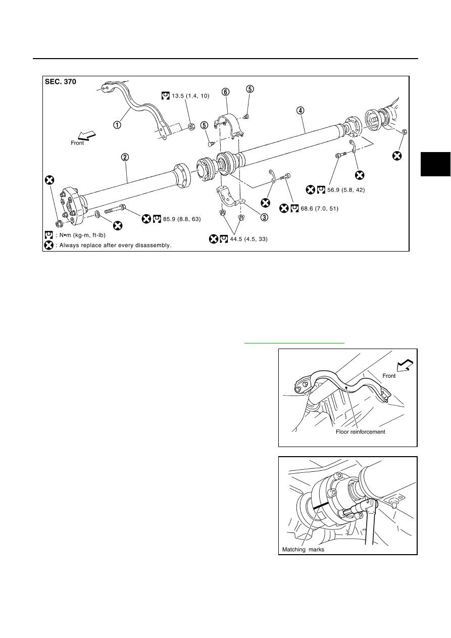
Components
NDS0005W
Removal and Installation
NDS0005X
REMOVAL
1.
Move A/T selector lever to N range position.
2.
Release parking brake.
3.
Remove exhaust front tube and center muffler. Refer to
4.
Remove floor reinforcement.
5.
Put matching marks on propeller shaft rubber coupling with
transmission companion flange and on rebro joint with final drive
companion flange.
CAUTION:
For matching mark, use paint. Do not damage rubber cou-
pling, rebro joint and companion flanges.
1.
Floor reinforcement
2.
Propeller shaft (1st shaft)
3.
Center bearing mounting bracket
(Lower)
4.
Propeller shaft (2nd shaft)
5.
Clip
6.
Center bearing mounting bracket
(Upper)
PDIA0468E
PDIA0401E
PDIA0470E