Infiniti Q45. Manual - part 619


  Index      Infiniti     Infiniti Q45 - service repair manual 2006 year


Search            copyright infringement  


Content   ..  617  618  619  620   ..


Infiniti Q45. Manual - part 619


REAR WINDOW DEFOGGER

GW-69

C

D

E

F

G

H

J

K

L

M

A

B

GW

5.

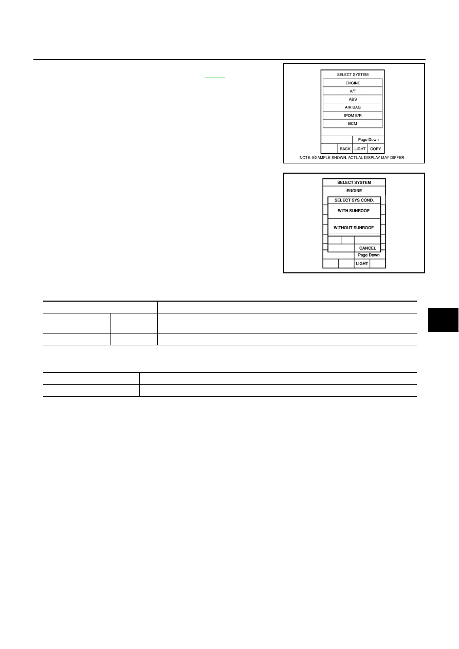
Touch “IVMS”on the “SELECT SYSTEM” screen.
If “IVMS” is not indicated, go to Refer to 

GI-37

 ,“CONSULT-II

Date Link Connector (DLC) Circuit”.

6.

Check the model specification, and touch either “WITH SUN-
ROOF” or “WITHOUT SUNROOF” on the “SELECT SYS
COND” screen.

7.

Touch “OK”. If the selection is wrong, touch “CANCEL”.

8.

Select the desired part to be diagnosed on the “SELECT TEST
ITEM” screen.

DATA MONITOR
Display Item List

ACTIVE TEST
Display Item List

BCIA0030E

PIIA0184E

Monitor item “Operation”

Content

REAR DEF SW

“ON/OFF”

Displays “Press (ON)/others (OFF)” status determined with the rear window defogger 
switch.

IGN ON SW

“ON/OFF”

Displays “IGN (ON)/OFF” status determined with the ignition switch signal.

Test item

Content

REAR DEFOGGER

Gives a drive signal to the rear window defogger to activate it.

GW-70

REAR WINDOW DEFOGGER

Trouble Diagnoses Symptom Chart

NIS000ZM

Check that other systems using the signal of the following systems operate normally.

 Check Rear Window Defogger Switch Circuit.

NIS000ZN

1. 

CHECK REAR WINDOW DEFOGGER (MULTIFUNCTION) SWITCH 

 With CONSULT-II

Check rear window defogger switch “REAR DEF SW” in the “DATA
MONITOR” mode with CONSULT-II, Refer to 

GW-69, "DATA MONI-

TOR"

 .

 With out CONSULT-II

1.

Turn ignition switch ON.

2.

Check voltage between BCM connector and ground.

OK or NG

OK

>> Rear window defogger switch is OK.

NG

>> GO TO 2

Symptom

Diagnoses / service procedure

Refer to page

Rear window defogger and door mirror defogger do not 
operate.

1. Check rear window defogger switch circuit.

GW-70

2. Check rear window defogger and door mirror defogger 
circuit.

GW-71

Rear window defogger does not operate but door mirror 
defogger operate.

1. Check rear window defogger circuit check.

GW-74

2. Check filament.

GW-78

Door mirror defogger does not operated, but rear win-
dow defogger operates.

1. Check door mirror defogger power supply circuit.

GW-75

Driver side door mirror defogger does not operated,
but other defogger operates.

1. Check driver side door mirror defogger circuit.

GW-77

Passenger side door mirror defogger does not operated,
but other defogger operates.

1. Check passenger side door mirror defogger circuit.

GW-78

When rear window defogger switch ON

REAR DEF SW

:ON

PIIB0510E

Connector

Terminal

(Wire color)

Condition of rear 

window defogger 

switch

Voltage [V]

(Approx)

(+)

(–)

M4

10 (BR)

Ground

ON

0

OFF

 5

PIIB2133E

REAR WINDOW DEFOGGER

GW-71

C

D

E

F

G

H

J

K

L

M

A

B

GW

2. 

REAR WINDOW DEFOGGER SWITCH SIGNAL CIRCUIT INSPECTION

1.

Turn ignition switch OFF.

2.

Disconnect BCM and multifunction switch (rear window defogger switch) connectors.

3.

Check continuity between BCM connector M4 terminal 10 and
multifunction switch (rear window defogger switch) connector
M83 terminal 5.

4.

Check continuity between BCM harness connector M4 terminal
10 and ground

OK or NG

OK

>> GO TO 3.

NG

>> Repair or replace harness.

3. 

MULTIFUNCTION (REAR WINDOW DEFOGGER) SWITCH GROUND HARNESS INSPECTION

Check continuity between multi-function switch (rear window defog-
ger switch) connector M83 terminal 2 and ground.

OK or NG

OK

>> Replace multi function switch.

NG

>> Repair or replace harness.

Check Rear Window Defogger and Door Mirror Defogger Circuit

NIS000ZO

1. 

CHECK FUSE 

Check if any of the following fuses for Fuse block (J/B) are blown.

NOTE:
Refer to

GW-61, "Component Parts and Harness Connector Location"

 .

OK or NG

OK

>> GO TO 2.

NG

>> If fuse is blown, be sure to eliminate cause of malfunction before installing new fuse, refer to

PG-2,

"POWER SUPPLY ROUTING"

 .

10 (BR) – 5 (BR) 

:Continuity should exist

10 (BR) – Ground 

:Continuity should not exist

PIIA2885E

2 (B) 

 Ground

:Continuity should exist

PIIA3514E

System

Terminal No. (signal)

Power source

Fuse No.

Ampere (A)

Rear defogger

8H

Battery power supply

10

20

3H

Battery power supply

11

20

2J

Ignition power supply

1

10

GW-72

REAR WINDOW DEFOGGER

2. 

CHECK REAR WINDOW DEFOGGER AND DOOR MIRROR DEFOGGER RELAY POWER SUPPLY 

CIRCUIT 

1.

Turn ignition switch OFF.

2.

Disconnect rear window defogger and door mirror defogger relay.

3.

Check voltage between rear window defogger and door mirror defogger relay connector and ground.

OK or NG

OK

>> GO TO 3.

NG

>> Check harness for open or short between rear window

defogger and door mirror defogger relay and fuse.

3. 

REAR WINDOW DEFOGGER AND DOOR MIRROR DEFOGGER RELAY INSPECTION

 With CONSULT-II

1.

Connect the rear window defogger and door mirror defogger relay.

2.

Check rear window defogger and door mirror defogger relay
“REAR DEFOGGER RLY” in the ACTIVE TEST mode with
CONSULT-II, Refer to 

GW-69, "ACTIVE TEST"

 , check the oper-

ation. 

 Without CONSULT-II

Check continuity between rear window defogger and door mirror
defogger relay terminals 3 and 5, 6 and 7.

OK or NG

OK

>> GO TO 4.

NG

>> Replace rear window defogger and door mirror defogger relay.

Connector

Terminals (Wire color)

Condition of 

ignition switch

Voltage [V]

(Approx.)

(+)

(–)

B8

1 (W/G)

Ground

 OFF

Battery
voltage

3 (R/B)

 ON

6 (L)

 OFF

PIIB0316E

The operation sound of rear defogger relay is 
confirmed.

PIIA0208E

Terminal

Condition

Continuity

3

5

12V direct current supply 
between terminals 1 to 2

Yes

No current supply

No

6

7

12V direct current supply 
between terminals 1 to 2

Yes

No current supply

No

SEC202B


Content   ..  617  618  619  620   ..