Infiniti Q45. Manual - part 577
EXHAUST SYSTEM
EX-5
C
D
E
F
G
H
I
J
K
L
M
A
EX
●
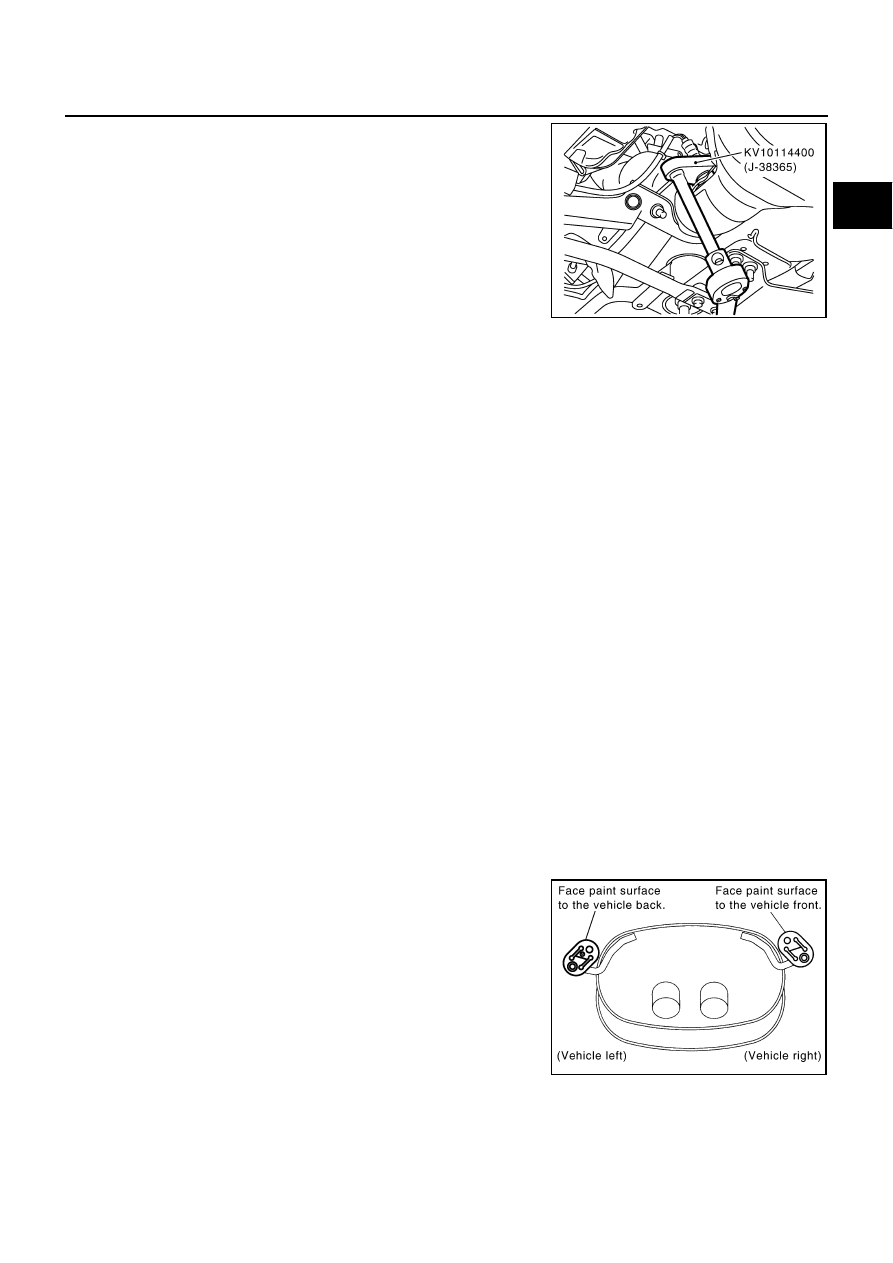
Using heated oxygen sensor wrench (SST), remove heated
oxygen sensor 2 (bank1 and bank2).
CAUTION:
Be careful not to damage heated oxygen sensor.
NOTE:
Figure is shown as an example of right bank.
3.
Disconnect each joint and mounting rubber using power tool.
Models with rear active steer
●
Remove U-clamp.
●
Remove nut, then remove serration bolt.
●
Remove main muffler from the center muffler.
INSTALLATION
Note the following, and install in the reverse order of removal.
CAUTION:
●
Always replace exhaust gaskets with new ones when reassembling.
●
Discard any heated oxygen sensor which has been dropped onto a hard surface such as a con-
crete floor; use a new one.
●
Before installing a new heated oxygen sensor, clean exhaust system threads using the heated
oxygen sensor thread cleaner [commercial service tool: J-43897-18 or J-43897-12], and apply the
anti-seize lubricant (commercial service tool).
●
Do not over torque heated oxygen sensor. Doing so may cause damage to heated oxygen sensor,
resulting in the “MIL” coming on.
●
If the insulator is badly deformed, repair or replace it. If deposits such as mud pile up on the insu-
lator, remove them.
●
When installing insulator avoid large gaps or interference between insulator and each exhaust
pipe.
●
Remove deposits and left over gasket material from the sealing surface of each connection. Con-
nect them securely to avoid gas leakage.
●
Temporarily tighten mounting nuts on the exhaust manifold side and mounting bolts on the vehi-
cle side. Make sure that each part for unusual interference, and then tighten them to the specified
torque.
●
When installing each mounting rubber, avoid twisting or unusual extension in up/down and right/
left directions.
●
Install mounting rubbers on rear main muffler as shown.
INSPECTION AFTER INSTALLATION
Note the following, and install in the reverse order of removal.
●
Make sure that clearance between tail tube and bumper is even.
●
With engine running, make sure that exhaust tube joints for gas leakage and unusual noises.
PBIC2671E
PBIC2868E