Infiniti Q45. Manual - part 510
DTC P2A00, P2A03 A/F SENSOR 1
EC-679
C
D
E
F
G
H
I
J
K
L
M
A
EC
Specification data are reference values and are measured between each terminal and ground.
Pulse signal is measured by CONSULT-II.
CAUTION:
Do not use ECM ground terminals when measuring input/output voltage. Doing so may result in dam-
age to the ECM's transistor. Use a ground other than ECM terminals, such as the ground.
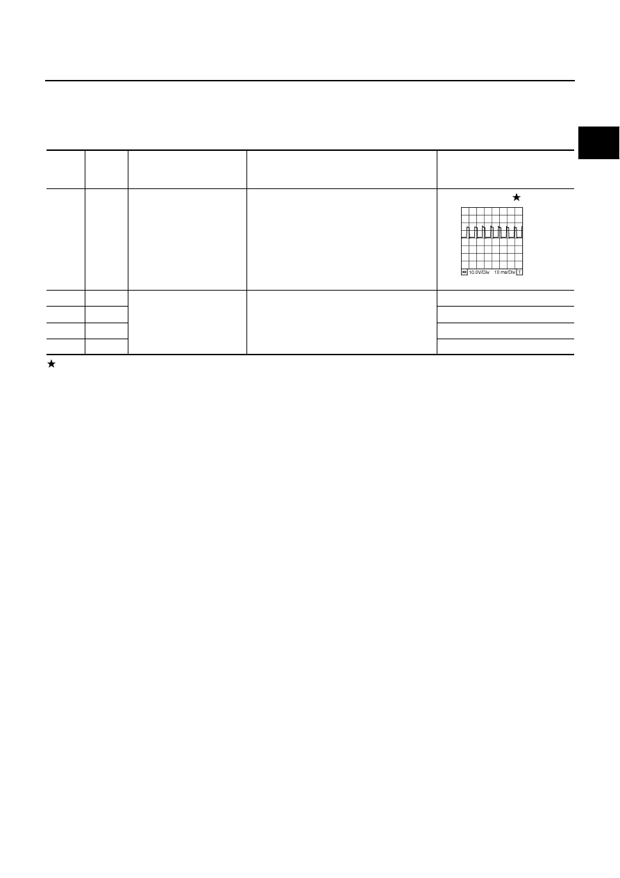
: Average voltage for pulse signal (Actual pulse signal can be confirmed by oscilloscope.)
TER-
MINAL
NO.
WIRE
COLOR
ITEM
CONDITION
DATA (DC Voltage)
2
OR
A/F sensor 1 heater
(bank 1)
[Engine is running]
●
Warm-up condition
●
Idle speed
Approximately 5V
16
W
A/F sensor 1 (bank 1)
[Engine is running]
●
Warm-up condition
●
Idle speed
Approximately 3.1V
35
R
Approximately 2.6V
56
R/L
Approximately 2.3V
75
BR
Approximately 2.3V
PBIB1584E