Infiniti Q45. Manual - part 503


  Index      Infiniti     Infiniti Q45 - service repair manual 2006 year


Search            copyright infringement  


Content   ..  501  502  503  504   ..


Infiniti Q45. Manual - part 503


DTC P2122, P2123 APP SENSOR

EC-651

C

D

E

F

G

H

I

J

K

L

M

A

EC

2. 

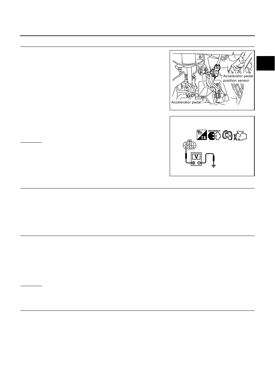
CHECK APP SENSOR 1 POWER SUPPLY CIRCUIT

1.

Disconnect accelerator pedal position (APP) sensor harness
connector.

2.

Turn ignition switch ON.

3.

Check voltage between APP sensor terminal 6 and ground with
CONSULT-II or tester.

OK or NG

OK

>> GO TO 4.

NG

>> GO TO 3.

3. 

DETECT MALFUNCTIONING PART

Check the following.

Harness connectors M135, F105

Harness for open or short between ECM and accelerator pedal position sensor

>> Repair open circuit or short to ground or short to power in harness or connectors.

4. 

CHECK APP SENSOR 1 GROUND CIRCUIT FOR OPEN AND SHORT

1.

Turn ignition switch OFF.

2.

Disconnect ECM harness connector.

3.

Check harness continuity between APP sensor terminal 3 and ECM terminal 82.
Refer to Wiring Diagram.

4.

Also check harness for short to ground and short to power.

OK or NG

OK

>> GO TO 6.

NG

>> GO TO 5.

5. 

DETECT MALFUNCTIONING PART

Check the following.

Harness connectors M135, F105

Harness for open or short between ECM and accelerator pedal position sensor

>> Repair open circuit or short to ground or short to power in harness or connectors.

PBIB2432E

Voltage: Approximately 5V

PBIB0914E

Continuity should exist.

EC-652

DTC P2122, P2123 APP SENSOR

6. 

CHECK APP SENSOR INPUT SIGNAL CIRCUIT FOR OPEN AND SHORT

1.

Check harness continuity between ECM terminal 106 and APP sensor terminal 5.
Refer to Wiring Diagram.

2.

Also check harness for short to ground and short to power.

OK or NG

OK

>> GO TO 8.

NG

>> GO TO 7.

7. 

DETECT MALFUNCTIONING PART

Check the following.

Harness connectors M135, F105

Harness for open or short between ECM and accelerator pedal position sensor

>> Repair open circuit or short to ground or short to power in harness or connectors.

8. 

CHECK APP SENSOR

Refer to 

EC-652, "Component Inspection"

 .

OK or NG

OK

>> GO TO 10.

NG

>> GO TO 9.

9. 

REPLACE ACCELERATOR PEDAL ASSEMBLY

1.

Replace accelerator pedal assembly.

2.

Perform 

EC-77, "Accelerator Pedal Released Position Learning"

 .

3.

Perform 

EC-78, "Throttle Valve Closed Position Learning"

 .

4.

Perform 

EC-78, "Idle Air Volume Learning"

 .

>> INSPECTION END

10. 

CHECK INTERMITTENT INCIDENT

Refer to 

EC-145, "TROUBLE DIAGNOSIS FOR INTERMITTENT INCIDENT"

 .

>> INSPECTION END

Component Inspection

NBS00263

ACCELERATOR PEDAL POSITION SENSOR

1.

Reconnect all harness connectors disconnected.

2.

Turn ignition switch ON.

3.

Check voltage between ECM terminals 106 (APP sensor 1 sig-
nal), 98 (APP sensor 2 signal) and ground under the following
conditions.

Continuity should exist.

Terminal

Accelerator pedal

Voltage

106
 (Accelerator pedal position 
sensor 1)

Fully released

0.5 - 1.0V

Fully depressed

3.9 - 4.7V

98
(Accelerator pedal position 
sensor 2)

Fully released

0.15 - 0.60V

Fully depressed

1.95 - 2.40V

MBIB0023E

DTC P2122, P2123 APP SENSOR

EC-653

C

D

E

F

G

H

I

J

K

L

M

A

EC

4.

If NG, replace accelerator pedal assembly and go to next step.

5.

Perform 

EC-77, "Accelerator Pedal Released Position Learning"

 .

6.

Perform 

EC-78, "Throttle Valve Closed Position Learning"

 .

7.

Perform 

EC-78, "Idle Air Volume Learning"

 .

Removal and Installation

NBS00264

ACCELERATOR PEDAL

Refer to 

ACC-3, "ACCELERATOR CONTROL SYSTEM"

 .

EC-654

DTC P2127, P2128 APP SENSOR

DTC P2127, P2128 APP SENSOR

PFP:18002

Component Description

NBS00265

The accelerator pedal position sensor is installed on the upper end
of the accelerator pedal assembly. The sensor detects the accelera-
tor position and sends a signal to the ECM.
Accelerator pedal position sensor has two sensors. These sensors
are a kind of potentiometers which transform the accelerator pedal
position into output voltage, and emit the voltage signal to the ECM.
In addition, these sensors detect the opening and closing speed of
the accelerator pedal and feed the voltage signals to the ECM. The
ECM judges the current opening angle of the accelerator pedal from
these signals and controls the throttle control motor based on these
signals.
Idle position of the accelerator pedal is determined by the ECM
receiving the signal from the accelerator pedal position sensor. The ECM uses this signal for the engine oper-
ation such as fuel cut.

CONSULT-II Reference Value in Data Monitor Mode

NBS00266

Specification data are reference values.

*: Accelerator pedal position sensor 2 signal is converted by ECM internally. Thus, it differs from ECM terminal voltage.

On Board Diagnosis Logic

NBS00267

These self-diagnoses have the one trip detection logic.

FAIL-SAFE MODE

When the malfunction is detected, ECM enters fail-safe mode and the MIL lights up.

PBIB1741E

MONITOR ITEM

CONDITION

SPECIFICATION

ACCEL SEN 1

Ignition switch: ON
(engine stopped)

Accelerator pedal: Fully released

0.5 - 1.0V

Accelerator pedal: Fully depressed

4.0 - 4.8V

ACCEL SEN 2*

Ignition switch: ON
(engine stopped)

Accelerator pedal: Fully released

0.3 - 1.2V

Accelerator pedal: Fully depressed

3.9 - 4.8V

CLSD THL POS

Ignition switch: ON
(Engine stopped)

Accelerator pedal: Fully released

ON

Accelerator pedal: Slightly depressed

OFF

DTC No.

Trouble diagnosis name

DTC detecting condition

Possible cause

P2127
2127

Accelerator pedal posi-
tion sensor 2 circuit low 
input

An excessively low voltage from the APP sen-
sor 2 is sent to ECM.

Harness or connectors
(APP sensor 2 circuit is open or 
shorted.)
(TP sensor circuit is shorted.)

Accelerator pedal position sensor
(Accelerator pedal position sensor 2)

Electric throttle control actuator
(TP sensor 1 and 2)

P2128
2128

Accelerator pedal posi-
tion sensor 2 circuit high 
input

An excessively high voltage from the APP sen-
sor 2 is sent to ECM.

Engine operating condition in fail-safe mode

The ECM controls the electric throttle control actuator in regulating the throttle opening in order for the idle position to be within +10 
degrees.
The ECM regulates the opening speed of the throttle valve to be slower than the normal condition.
So, the acceleration will be poor. 


Content   ..  501  502  503  504   ..