Infiniti Q45. Manual - part 464


  Index      Infiniti     Infiniti Q45 - service repair manual 2006 year


Search            copyright infringement  


Content   ..  462  463  464  465   ..


Infiniti Q45. Manual - part 464


DTC P0643 SENSOR POWER SUPPLY

EC-495

C

D

E

F

G

H

I

J

K

L

M

A

EC

Diagnostic Procedure

NBS0022J

1. 

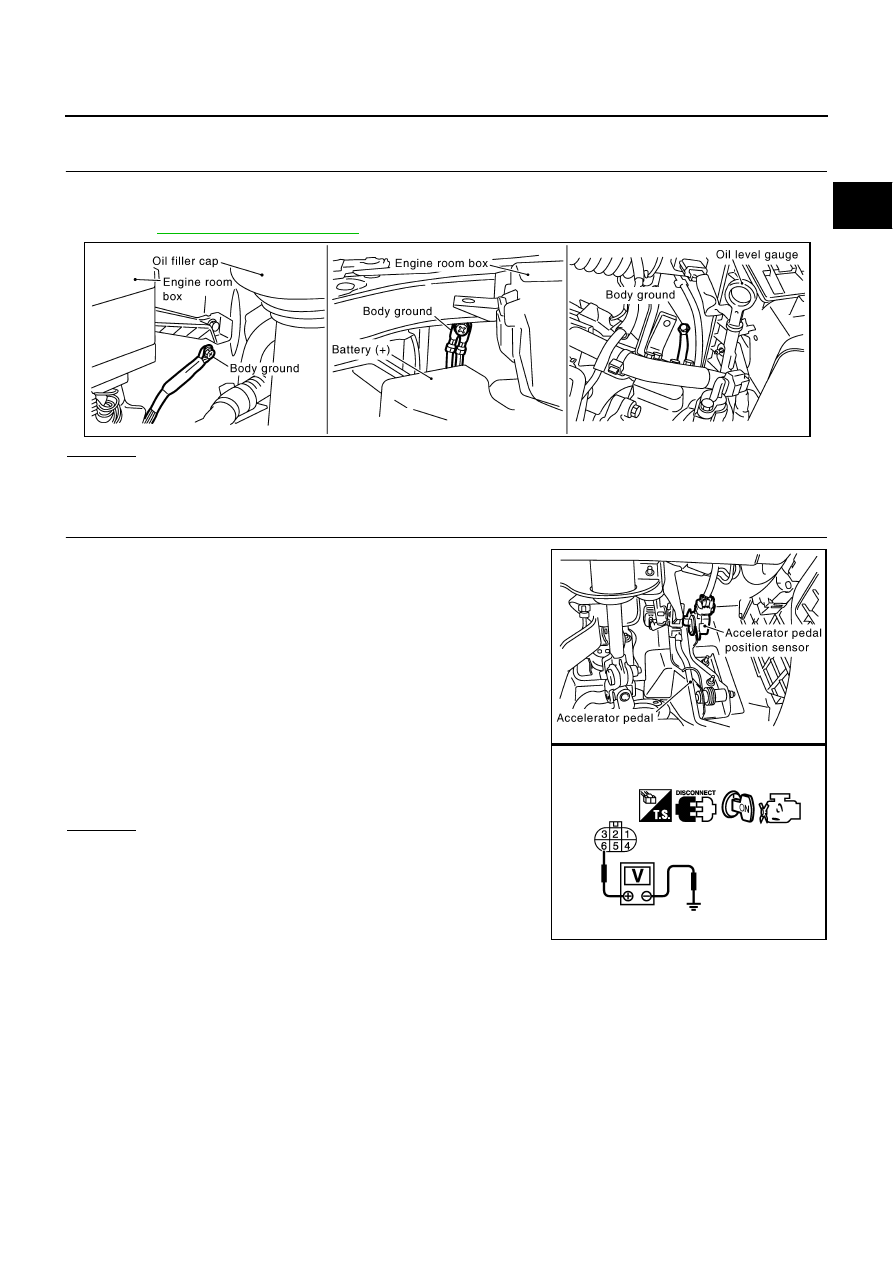
CHECK GROUND CONNECTIONS

1.

Turn ignition switch OFF.

2.

Loosen and retighten three ground screws on the body.
Refer to 

EC-154, "Ground Inspection"

 .

OK or NG

OK

>> GO TO 2.

NG

>> Repair or replace ground connections.

2. 

CHECK ACCELERATOR PEDAL POSITION SENSOR 1 POWER SUPPLY CIRCUIT

1.

Disconnect accelerator pedal position (APP) sensor harness
connector.

2.

Turn ignition switch ON.

3.

Check voltage between APP sensor terminal 6 and ground with
CONSULT-II or tester.

OK or NG

OK

>> GO TO 5.

NG

>> GO TO 3.

PBIB2417E

Voltage: Approximately 5V

PBIB2432E

PBIB0914E

EC-496

DTC P0643 SENSOR POWER SUPPLY

3. 

CHECK SENSOR POWER SUPPLY CIRCUITS

Check harness for short to power and short to ground, between the following terminals.

OK or NG

OK

>> GO TO 4.

NG

>> Repair short to ground or short to power in harness or connectors.

4. 

CHECK COMPONENTS

Check the following.

EVAP control pressure sensor (Refer to 

EC-442, "Component Inspection"

 .)

Refrigerant pressure sensor (Refer to 

ATC-92, "COMPONENT INSPECTION"

 .)

Power steering pressure sensor (Refer to 

EC-484, "Component Inspection"

 .)

OK or NG

OK

>> GO TO 7.

NG

>> Replace malfunctioning component.

5. 

CHECK APP SENSOR

Refer to 

EC-652, "Component Inspection"

 .

OK or NG

OK

>> GO TO 7.

NG

>> GO TO 6.

6. 

REPLACE ACCELERATOR PEDAL ASSEMBLY

1.

Replace accelerator pedal assembly.

2.

Perform 

EC-77, "Accelerator Pedal Released Position Learning"

 .

3.

Perform 

EC-78, "Throttle Valve Closed Position Learning"

 .

4.

Perform 

EC-78, "Idle Air Volume Learning"

 .

>> INSPECTION END

7. 

CHECK INTERMITTENT INCIDENT

Refer to 

EC-145, "TROUBLE DIAGNOSIS FOR INTERMITTENT INCIDENT"

 .

>> INSPECTION END

ECM terminal

Sensor terminal

Reference Wiring Diagram

90

APP sensor terminal 6

EC-493

48

EVAP control pressure sensor terminal 1

EC-438

49

Refrigerant pressure sensor terminal 1

EC-745

68

PSP sensor terminal 1

EC-481

DTC P0850 PNP SWITCH

EC-497

C

D

E

F

G

H

I

J

K

L

M

A

EC

DTC P0850 PNP SWITCH

PFP:23006

Component Description

NBS0024Y

When the selector lever position is P or N, park/neutral position (PNP) switch is ON.
ECM detects the position because the continuity of the line (the “ON” signal) exists.

CONSULT-II Reference Value in Data Monitor Mode

NBS0024Z

Specification data are reference values.

On Board Diagnosis Logic

NBS00250

DTC Confirmation Procedure

NBS00251

CAUTION:

Always drive vehicle at a safe speed.

NOTE:
If DTC Confirmation Procedure has been previously conducted, always turn ignition switch OFF and wait at
least 10 seconds before conducting the next test.

 WITH CONSULT-II

1.

Turn ignition switch ON.

2.

Select “P/N POSI SW” in “DATA MONITOR” mode with CON-
SULT-II. Then check the “P/N POSI SW” signal under the follow-
ing conditions.

If NG, go to 

EC-500, "Diagnostic Procedure"

 .

If OK, go to following step.

3.

Select “DATA MONITOR” mode with CONSULT-II.

4.

Start engine and warm it up to normal operating temperature.

5.

Maintain the following conditions for at least 60 consecutive sec-
onds.

6.

If 1st trip DTC is detected, go to 

EC-500, "Diagnostic Procedure"

.

MONITOR ITEM

CONDITION

SPECIFICATION

P/N POSI SW

Ignition switch: ON

Selector lever: P or N

ON

Selector lever: Except above

OFF

DTC No.

Trouble diagnosis name

DTC detecting condition

Possible cause

P0850
0850

Park/neutral position 
switch

The signal of the park/neutral position (PNP) 
switch is not changed in the process of engine 
starting and driving.

Harness or connectors
[The park/neutral position (PNP) switch 
circuit is open or shorted.]

Park/neutral position (PNP) switch

TCM

Position (Selector lever)

Known-good signal

N or P position

ON

Except above position

OFF

ENG SPEED

More than 1,200 rpm

COOLAN TEMP/S

More than 70

°

C (158

°

F)

B/FUEL SCHDL

2.0 - 31.8 msec

VHCL SPEED SE

More than 64 km/h (40 MPH)

Selector lever

Suitable position

SEF212Y

SEF213Y

EC-498

DTC P0850 PNP SWITCH

Overall Function Check

NBS00252

Use this procedure to check the overall function of the park/neutral position (PNP) switch circuit. During this
check, a 1st trip DTC might not be confirmed.

 WITH GST

1.

Turn ignition switch ON.

2.

Check voltage between ECM terminal 102 (PNP switch signal)
and ground under the following conditions.

3.

If NG, go to 

EC-500, "Diagnostic Procedure"

 .

Position (Selector lever)

Voltage (Known good data)

P or N position

Approx. 0V

Except above position

BATTERY VOLTAGE (11 - 14V)

MBIB0043E


Content   ..  462  463  464  465   ..