Infiniti Q45. Manual - part 458
DTC P0461 FUEL LEVEL SENSOR
EC-471
C
D
E
F
G
H
I
J
K
L
M
A
EC
7.
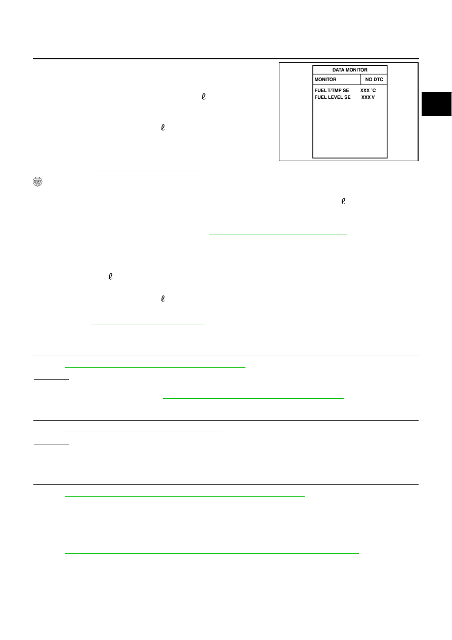
Check “FUEL LEVEL SE” output voltage and note it.
8.
Select “FUEL PUMP” in “ACTIVE TEST” mode with CONSULT-
II.
9.
Touch ON and drain fuel approximately 30 (7-7/8 US gal, 6-5/
8 Imp gal) and stop it.
10. Check “FUEL LEVEL SE” output voltage and note it.
11. Fill fuel into the fuel tank for 30 (7-7/8 US gal, 6-5/8 Imp gal).
12. Check “FUEL LEVEL SE” output voltage and note it.
13. Confirm whether the voltage changes more than 0.03V during
step 7 to 10 and 10 to 12.
If NG, go to
EC-471, "Diagnostic Procedure"
WITH GST
NOTE:
Start from step 8, if it is possible to confirm that the fuel cannot be drained by 30 (7-7/8 US gal, 6-5/8
Imp gal) in advance.
1.
Prepare a fuel container and a spare hose.
2.
Release fuel pressure from fuel line. Refer to
EC-80, "FUEL PRESSURE RELEASE"
3.
Remove the fuel feed hose on the fuel level sensor unit.
4.
Connect a spare fuel hose where the fuel feed hose was removed.
5.
Turn ignition switch ON.
6.
Drain fuel by 30 (7-7/8 US gal, 6-5/8 Imp gal) from the fuel tank using proper equipment.
7.
Confirm that the fuel gauge indication varies.
8.
Fill fuel into the fuel tank for 30 (7-7/8 US gal, 6-5/8 Imp gal).
9.
Confirm that the fuel gauge indication varies.
EC-471, "Diagnostic Procedure"
Diagnostic Procedure
NBS001YB
1.
CHECK FUEL GAUGE OPERATION
Refer to
DI-16, "Self-Diagnosis Mode of Combination Meter"
.
OK or NG
OK
>> GO TO 2.
NG
DI-16, "Self-Diagnosis Mode of Combination Meter"
2.
CHECK FUEL LEVEL SENSOR AND CIRCUIT
Refer to
DI-20, "Fuel Level Sensor Signal Inspection"
OK or NG
OK
>> GO TO 3.
NG
>> Repair or replace malfunctioning parts.
3.
CHECK INTERMITTENT INCIDENT
Refer to
EC-145, "TROUBLE DIAGNOSIS FOR INTERMITTENT INCIDENT"
>> INSPECTION END
Removal and Installation
NBS001YC
FUEL LEVEL SENSOR
Refer to
FL-3, "FUEL LEVEL SENSOR UNIT, FUEL FILTER AND FUEL PUMP ASSEMBLY"
SEF195Y