Infiniti Q45. Manual - part 452
DTC P0453 EVAP CONTROL SYSTEM PRESSURE SENSOR
EC-447
C
D
E
F
G
H
I
J
K
L
M
A
EC
2.
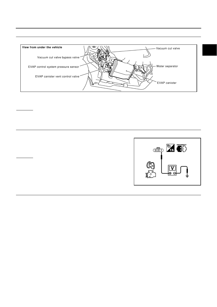
CHECK CONNECTOR
1.
Disconnect EVAP control system pressure sensor harness connector.
2.
Check sensor harness connector for water.
OK or NG
OK
>> GO TO 3.
NG
>> Repair or replace harness connector.
3.
CHECK EVAP CONTROL SYSTEM PRESSURE SENSOR POWER SUPPLY CIRCUIT
1.
Turn ignition switch ON.
2.
Check voltage between EVAP control system pressure sensor
terminal 1 and ground with CONSULT-II or tester.
OK or NG
OK
>> GO TO 5.
NG
>> GO TO 4.
4.
DETECT MALFUNCTIONING PART
Check the following.
●
Harness connectors B401, B251
●
Harness connectors B211, M141
●
Harness connectors M135, F105
●
Harness for open or short between EVAP control system pressure sensor and ECM
>> Repair open circuit or short to ground or short to power in harness or connectors.
Water should not exist.
PBIB0026E
Voltage: Approximately 5V
PBIB0155E