Infiniti Q45. Manual - part 436


  Index      Infiniti     Infiniti Q45 - service repair manual 2006 year


Search            copyright infringement  


Content   ..  434  435  436  437   ..


Infiniti Q45. Manual - part 436


DTC P0340 CMP SENSOR (PHASE)

EC-383

C

D

E

F

G

H

I

J

K

L

M

A

EC

2. 

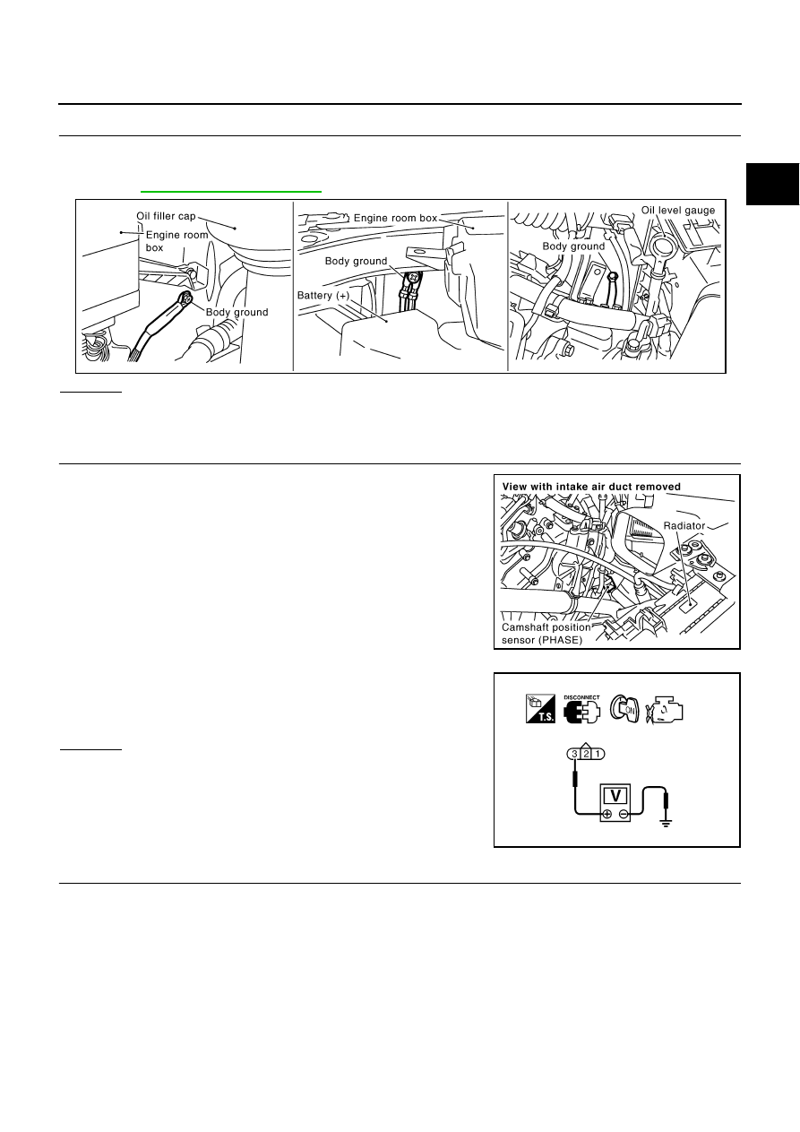
CHECK GROUND CONNECTIONS

1.

Turn ignition switch OFF.

2.

Loosen and retighten three ground screws on the body.
Refer to 

EC-154, "Ground Inspection"

 .

OK or NG

OK

>> GO TO 3.

NG

>> Repair or replace ground connections.

3. 

CHECK CAMSHAFT POSITION (CMP) SENSOR (PHASE) POWER SUPPLY CIRCUIT

1.

Disconnect camshaft position (CMP) sensor (PHASE) harness
connector.

2.

Turn ignition switch ON.

3.

Check voltage between CMP sensor (PHASE) terminal 3 and
ground with CONSULT-II or tester.

OK or NG

OK

>> GO TO 5.

NG

>> GO TO 4.

4. 

DETECT MALFUNCTIONING PART

Check the following.

Harness connectors F105, M135

Harness for open or short between ECM and camshaft position sensor (PHASE)

Harness for open or short between ECM relay and camshaft position sensor (PHASE)

>> Repair open circuit or short to ground or short to power in harness or connectors.

PBIB2417E

PBIB2419E

Voltage: Battery voltage

SEF481Y

EC-384

DTC P0340 CMP SENSOR (PHASE)

5. 

CHECK CMP SENSOR (PHASE) GROUND CIRCUIT FOR OPEN AND SHORT

1.

Turn ignition switch OFF.

2.

Check harness continuity between CMP sensor (PHASE) terminal 1 and ground.
Refer to Wiring Diagram.

3.

Also check harness for short to power.

OK or NG

OK

>> GO TO 7.

NG

>> GO TO 6.

6. 

DETECT MALFUNCTIONING PART

Check the following.

Harness connectors F32, E32

Harness for open or short between camshaft position sensor (PHASE) and ground

>> Repair open circuit or short to power in harness or connectors.

7. 

CHECK CMP SENSOR (PHASE) INPUT SIGNAL CIRCUIT FOR OPEN AND SHORT

1.

Disconnect ECM harness connector.

2.

Check harness continuity between ECM terminal 14 and CMP sensor (PHASE) terminal 2. 
Refer to Wiring Diagram.

3.

Also check harness for short to ground and short to power.

OK or NG

OK

>> GO TO 8.

NG

>> Repair open circuit or short to ground or short to power in harness or connectors.

8. 

CHECK CAMSHAFT POSITION SENSOR (PHASE)

Refer to 

EC-385, "Component Inspection"

 .

OK or NG

OK

>> GO TO 9.

NG

>> Replace camshaft position sensor (PHASE).

9. 

CHECK INTERMITTENT INCIDENT

Refer to 

EC-145, "TROUBLE DIAGNOSIS FOR INTERMITTENT INCIDENT"

 .

>> INSPECTION END

Continuity should exist.

Continuity should exist.

DTC P0340 CMP SENSOR (PHASE)

EC-385

C

D

E

F

G

H

I

J

K

L

M

A

EC

Component Inspection

NBS001WN

CAMSHAFT POSITION SENSOR (PHASE)

1.

Loosen the fixing bolt of the sensor.

2.

Disconnect camshaft position sensor (PHASE) harness connec-
tor.

3.

Remove the sensor.

4.

Visually check the sensor for chipping.

5.

Check resistance as shown in the figure.

Removal and Installation

NBS001WO

CAMSHAFT POSITION SENSOR (PHASE)

Refer to 

EM-39, "TIMING CHAIN"

 .

PBIB0563E

Terminal No. (Polarity)

Resistance 

 [at 25

°

C (77

°

F)]

3 (+) - 1 (-)

Except 0 or 

2 (+) - 1 (-)

3 (+) - 2 (-)

PBIB0564E

EC-386

DTC P0420, P0430 THREE WAY CATALYST FUNCTION

DTC P0420, P0430 THREE WAY CATALYST FUNCTION

PFP:20905

On Board Diagnosis Logic

NBS002XY

The ECM monitors the switching frequency ratio of air fuel ratio (A/F)
sensor 1 and heated oxygen sensor 2.
A three way catalyst (manifold) with high oxygen storage capacity
will indicate a low switching frequency of heated oxygen sensor 2.
As oxygen storage capacity decreases, the heated oxygen sensor 2
switching frequency will increase.
When the frequency ratio of A/F sensor 1 and heated oxygen sensor
2 approaches a specified limit value, the three way catalyst (mani-
fold) malfunction is diagnosed.

DTC Confirmation Procedure

NBS002XZ

NOTE:
If DTC Confirmation Procedure has been previously conducted, always turn ignition switch OFF and wait at
least 10 seconds before conducting the next test.

 WITH CONSULT-II

TESTING CONDITION:
Do not hold engine speed for more than the specified minutes below.

1.

Turn ignition switch ON and select “DATA MONITOR” mode with
CONSULT-II.

2.

Start engine and warm it up to the normal operating tempera-
ture.

3.

Turn ignition switch OFF and wait at least 10 seconds.

4.

Start engine and keep the engine speed between 3,500 and
4,000 rpm for at least 1 minute under no load.

5.

Let engine idle for 1 minute.

6.

Make sure that “COOLAN TEMP/S” indicates more than 70

°

C

(158

°

F).

If not, warm up engine and go to next step when “COOLAN
TEMP/S” indication reaches to 70

°

C (158

°

F).

7.

Open engine hood.

PBIB2055E

DTC No.

Trouble diagnosis name

DTC detecting condition

Possible cause

P0420
0420
(Bank 1)

Catalyst system effi-
ciency below threshold

Three way catalyst (manifold) does not oper-
ate properly.

Three way catalyst (manifold) does not have 
enough oxygen storage capacity.

Three way catalyst (manifold)

Exhaust tube

Intake air leaks

Fuel injector

Fuel injector leaks

Spark plug

Improper ignition timing

P0430
0430
(Bank 2)

SEF189Y


Content   ..  434  435  436  437   ..