Infiniti Q45. Manual - part 415


  Index      Infiniti     Infiniti Q45 - service repair manual 2006 year


Search            copyright infringement  


Content   ..  413  414  415  416   ..


Infiniti Q45. Manual - part 415


DTC P0138, P0158 HO2S2

EC-299

C

D

E

F

G

H

I

J

K

L

M

A

EC

2. 

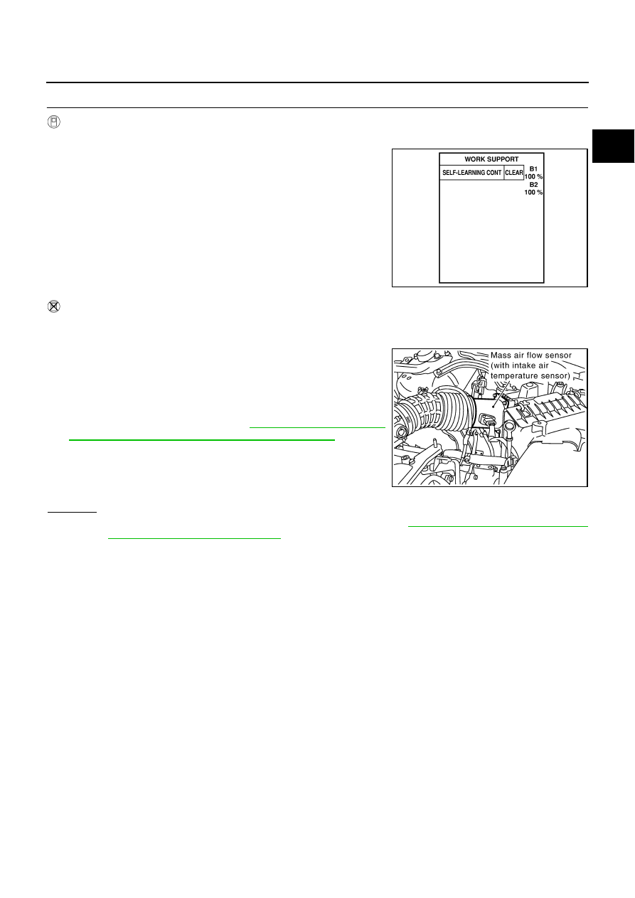
CLEAR THE SELF-LEARNING DATA

 With CONSULT-II

1.

Start engine and warm it up to normal operating temperature.

2.

Select “SELF-LEARNING CONT” in “WORK SUPPORT” mode
with CONSULT-II.

3.

Clear the self-learning control coefficient by touching “CLEAR”.

4.

Run engine for at least 10 minutes at idle speed.
Is the 1st trip DTC P0172 or P0175 detected?
Is it difficult to start engine?

 Without CONSULT-II

1.

Start engine and warm it up to normal operating temperature.

2.

Turn ignition switch OFF.

3.

Disconnect mass air flow sensor harness connector, and restart
and run engine for at least 5 seconds at idle speed.

4.

Stop engine and reconnect mass air flow sensor harness con-
nector.

5.

Make sure DTC P0102 is displayed.

6.

Erase the DTC memory. Refer to 

EC-61, "HOW TO ERASE

EMISSION-RELATED DIAGNOSTIC INFORMATION"

 .

7.

Make sure DTC P0000 is displayed.

8.

Run engine for at least 10 minutes at idle speed.
Is the 1st trip DTC P0172 or P0175 detected?
Is it difficult to start engine?

Yes or No

Yes

>> Perform trouble diagnosis for DTC P0172, P0175. Refer to 

EC-328, "DTC P0172, P0175 FUEL

INJECTION SYSTEM FUNCTION"

 .

No

>> GO TO 3.

SEF968Y

PBIB2418E

EC-300

DTC P0138, P0158 HO2S2

3. 

CHECK HO2S2 GROUND CIRCUIT FOR OPEN AND SHORT

1.

Turn ignition switch OFF.

2.

Disconnect heated oxygen sensor 2 harness connector.

3.

Disconnect ECM harness connector.

4.

Check harness continuity between HO2S2 terminal 4 and ECM terminal 78.
Refer to Wiring Diagram.

5.

Also check harness for short to ground and short to power.

OK or NG

OK

>> GO TO 5.

NG

>> GO TO 4.

4. 

DETECT MALFUNCTIONING PART

Check the following.

Harness connectors E315, F5

Harness for open or short between heated oxygen sensor 2 and ECM

>> Repair open circuit or short to ground or short to power in harness or connectors.

Continuity should exist.

PBIB0018E

DTC P0138, P0158 HO2S2

EC-301

C

D

E

F

G

H

I

J

K

L

M

A

EC

5. 

CHECK HO2S2 INPUT SIGNAL CIRCUIT FOR OPEN AND SHORT

1.

Check harness continuity between ECM terminal and HO2S2 terminal as follows.
Refer to Wiring Diagram.

2.

Check harness continuity between the following terminals and ground.
Refer to Wiring Diagram.

3.

Also check harness for short to ground and short to power.

OK or NG

OK

>> GO TO 7.

NG

>> GO TO 6.

6. 

DETECT MALFUNCTIONING PART

Check the following.

Harness connectors E315, F5

Harness for open or short between heated oxygen sensor 2 and ECM

>> Repair open circuit or short to ground or short to power in harness or connectors.

7. 

CHECK HEATED OXYGEN SENSOR 2

Refer to 

EC-302, "Component Inspection"

 .

OK or NG

OK

>> GO TO 8.

NG

>> Replace malfunctioning heated oxygen sensor 2.

8. 

CHECK INTERMITTENT INCIDENT

Refer to 

EC-145, "TROUBLE DIAGNOSIS FOR INTERMITTENT INCIDENT"

 .

>> INSPECTION END

DTC

Terminals

Bank

ECM

Sensor

P0138

55

1

1

P0158

74

1

2

Continuity should exist.

DTC

Terminals

Bank

ECM

Sensor

P0138

55

1

1

P0158

74

1

2

Continuity should not exist.

EC-302

DTC P0138, P0158 HO2S2

Component Inspection

NBS001UV

HEATED OXYGEN SENSOR 2

 With CONSULT-II

1.

Turn ignition switch ON and select “DATA MONITOR” mode with
CONSULT-II.

2.

Start engine and warm it up to the normal operating tempera-
ture.

3.

Turn ignition switch OFF and wait at least 10 seconds.

4.

Start engine and keep the engine speed between 3,500 and
4,000 rpm for at least 1 minute under no load.

5.

Let engine idle for 1 minute.

6.

Select “FUEL INJECTION” in “ACTIVE TEST” mode, and select
“HO2S2 (B1)/(B2)” as the monitor item with CONSULT-II.

7.

Check “HO2S2 (B1)/(B2)” at idle speed when adjusting “FUEL INJECTION” to 

±

25%.

“HO2S2 (B1)/(B2)” should be above 0.78V at least once when the “FUEL INJECTION” is +25%.
“HO2S2 (B1)/(B2)” should be below 0.18V at least once when the “FUEL INJECTION” is 

25%.

CAUTION:

Discard any heated oxygen sensor which has been dropped from a height of more than 0.5 m (19.7
in) onto a hard surface such as a concrete floor; use a new one.

Before installing new oxygen sensor, clean exhaust system threads using Oxygen Sensor Thread
Cleaner tool J-43897-18 or J-43897-12 and approved anti-seize lubricant.

 Without CONSULT-II

1.

Start engine and warm it up to the normal operating temperature.

2.

Turn ignition switch OFF and wait at least 10 seconds.

3.

Start engine and keep the engine speed between 3,500 and 4,000 rpm for at least 1 minute under no load.

4.

Let engine idle for 1 minute.

5.

Set voltmeter probes between ECM terminal 55 [HO2S2 (B1) signal] or 74 [HO2S2 (B2) signal] and
ground.

SEF174Y

PBIB1672E

PBIB2163E


Content   ..  413  414  415  416   ..