Infiniti Q45. Manual - part 378
POWER SUPPLY AND GROUND CIRCUIT
EC-151
C
D
E
F
G
H
I
J
K
L
M
A
EC
7.
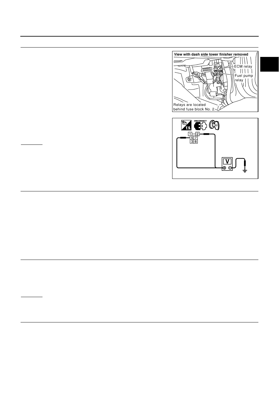
CHECK ECM POWER SUPPLY CIRCUIT-II
1.
Disconnect ECM relay.
2.
Check voltage between ECM relay terminals 2, 5 and ground
with CONSULT-II or tester.
OK or NG
OK
>> GO TO 9.
NG
>> GO TO 8.
8.
DETECT MALFUNCTIONING PART
Check the following.
●
10A fuse
●
20A fuse
●
Fuse block (J/B) No. 2 connector E215
●
Fuse, fusible link and relay block (J/B) connector E3
●
Harness for open or short between ECM relay and battery
>> Repair open circuit or short to ground or short to power in harness or connectors.
9.
CHECK OUTPUT SIGNAL CIRCUIT FOR OPEN AND SHORT
1.
Check harness continuity between ECM terminal 111 and ECM relay terminal 1.
Refer to Wiring Diagram.
2.
Also check harness for short to ground and short to power.
OK or NG
OK
>> GO TO 11.
NG
>> GO TO 10.
10.
DETECT MALFUNCTIONING PART
Check the following.
●
Harness connectors M135, F105
●
Fuse block (J/B) No. 2 connector M143
●
Harness for open or short between ECM relay and ECM
>> Repair open circuit or short to ground or short to power in harness or connectors.
PBIB0040E
Voltage: Battery voltage
PBIB0071E
Continuity should exist.