Infiniti Q45. Manual - part 332
REAR VIEW MONITOR
DI-195
C
D
E
F
G
H
I
J
L
M
A
B
DI
2.
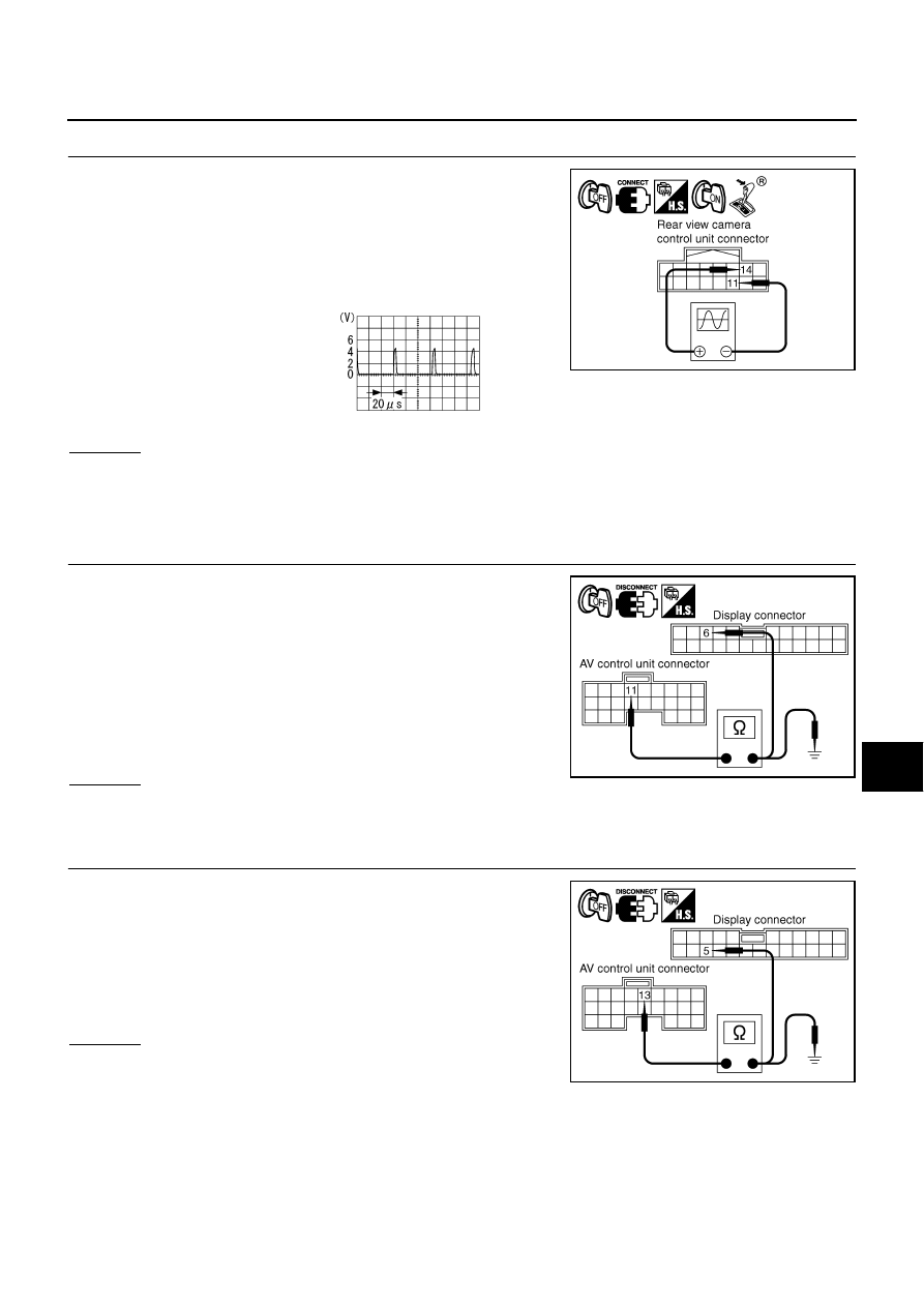
CHECK REAR VIEW CAMERA CONTROL UNIT COMPOSITE SYNCHRONIZING SIGNAL
1.
Connect rear view camera control unit connector and display
connector.
2.
Turn ignition switch ON.
3.
Shift A/T selector lever to “R” position.
4.
Check voltage signal between rear view camera control unit har-
ness connector B236 terminals 14 and 11.
OK or NG
OK
>>
●
GO TO 3 (without NAVI).
●
GO TO 7 (with NAVI).
NG
>> Replace rear view camera control unit.
3.
CHECK AV CONTROL UNIT VERTICAL SYNCHRONIZING SIGNAL CIRCUIT
1.
Turn ignition switch OFF.
2.
Disconnect AV control unit connector and display connector.
3.
Check continuity between AV control unit harness connector
M78 terminal 11 and display harness connector M82 terminal 6.
4.
Check continuity between AV control unit harness connector
M78 terminal 11 and ground.
OK or NG
OK
>> GO TO 4.
NG
>> Repair harness or connector.
4.
CHECK AV CONTROL UNIT HORIZONTAL SYNCHRONIZING SIGNAL CIRCUIT
1.
Check continuity between AV control unit harness connector
M78 terminal 13 and display harness connector M82 terminal 5.
2.
Check continuity between AV control unit harness connector
M78 terminal 13 and ground.
OK or NG
OK
>> GO TO 5.
NG
>> Repair harness or connector.
14 – 11:
SKIB0719E
SKIA5896E
11 – 6
: Continuity should exist.
11 – Ground
: Continuity should not exist.
SKIB0720E
13 – 5
: Continuity should exist.
13 – Ground
: Continuity should not exist.
SKIB0721E