Infiniti Q45. Manual - part 318
VEHICLE INFORMATION AND INTEGRATED SWITCH SYSTEM /WITHOUT
NAVIGATION SYSTEM
DI-139
C
D
E
F
G
H
I
J
L
M
A
B
DI
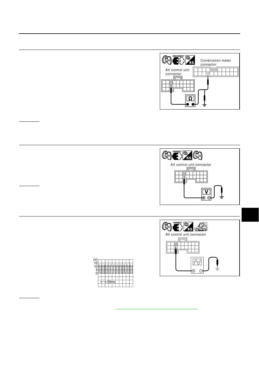
Vehicle Speed Signal Inspection
NKS001CV
1.
CHECK HARNESS
1.
Turn ignition switch OFF.
2.
Disconnect AV control unit connector and combination meter
connector.
3.
Check continuity between AV control unit harness connector
M77 terminal 33 and combination meter harness connector M41
terminal 17.
4.
Check continuity between AV control unit harness connector
M77 terminal 33 and ground.
OK or NG
OK
>> GO TO 2.
NG
>> Repair harness or connector.
2.
CHECK OUTPUT VOLTAGE
1.
Connect AV control unit connector.
2.
Turn ignition switch ON.
3.
Check voltage between AV control unit harness connector M77
terminal 33 and ground.
OK or NG
OK
>> GO TO 3.
NG
>> Replace AV control unit.
3.
CHECK VEHICLE SPEED SIGNAL
1.
Turn ignition switch OFF and connect combination meter con-
nector.
2.
Start engine and drive vehicle at approximately 40 km/h (25
MPH).
3.
Check voltage signal between AV control unit harness connector
M77 terminal 33 and ground.
OK or NG
OK
>> Replace AV control unit.
NG
>> Check combination meter. Refer to
DI-18, "Vehicle Speed Signal Inspection"
.
33 – 17
: Continuity should exist.
33 – Ground
: Continuity should not exist.
PKIA9691E
33 – Ground
: Approx. 3.5 V or more
PKIA9692E
33 – Ground:
PKIA9693E
PKIA1935E