Infiniti Q45. Manual - part 273
TROUBLE DIAGNOSIS FOR SYSTEM
BRC-57
[VDC/TCS/ABS]
C
D
E
G
H
I
J
K
L
M
A
B
BRC
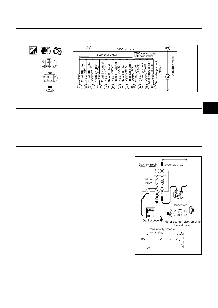
VDC ACTUATOR
Turn ignition switch OFF and Disconnect VDC actuator connectors. Check continuity and resistance value
between any pair of terminals on the actuator.
CAUTION:
Make sure actuator motor is correctly grounded.
Continuity and resistance
Actuator Operation Inspection
●
Turn ignition switch OFF, apply a voltage of 12 V between VDC
relay box connector E56 terminal 5 and 8, use an oscilloscope
to measure motor voltage at this time (between terminal 4 and
ground), and check motor reverse voltage occurrence time
when operation is stopped.
CAUTION:
●
Above check should be performed after motor relay unit
inspection to make sure relay operates normally.
●
To prevent overheating, do not drive actuator motor more
than 4 seconds.
●
Motor reverse voltage occurrence time is standard when
battery voltage is 12 V and the air temperature is 20
°
C
(68
°
F), and this time is a little shorter when battery voltage
is low or the air temperature is low.
SFIA2339E
Item
VDC actuator connector terminal num-
ber
Continuity and Resistance
value
Condition
Solenoid valve
1, 3, 5, 7
19
6.0 - 11
Ω
Check the resistance
14, 15, 16, 17
3.0 - 5.0
Ω
VDC switch-over solenoid
valve
25, 26
6.0 - 11
Ω
27, 28
3.0 - 5.0
Ω
Actuator motor
21
ground
Yes
—
Motor counter electromotive force duration
: 0.1 second or more
SFIA3313E