Infiniti Q45. Manual - part 270
TROUBLE DIAGNOSIS FOR SYSTEM
BRC-45
[VDC/TCS/ABS]
C
D
E
G
H
I
J
K
L
M
A
B
BRC
3.
CHECK SOLENOID AND VDC SWITCHING VALVE CIRCUIT
1.
Turn ignition switch “OFF”.
2.
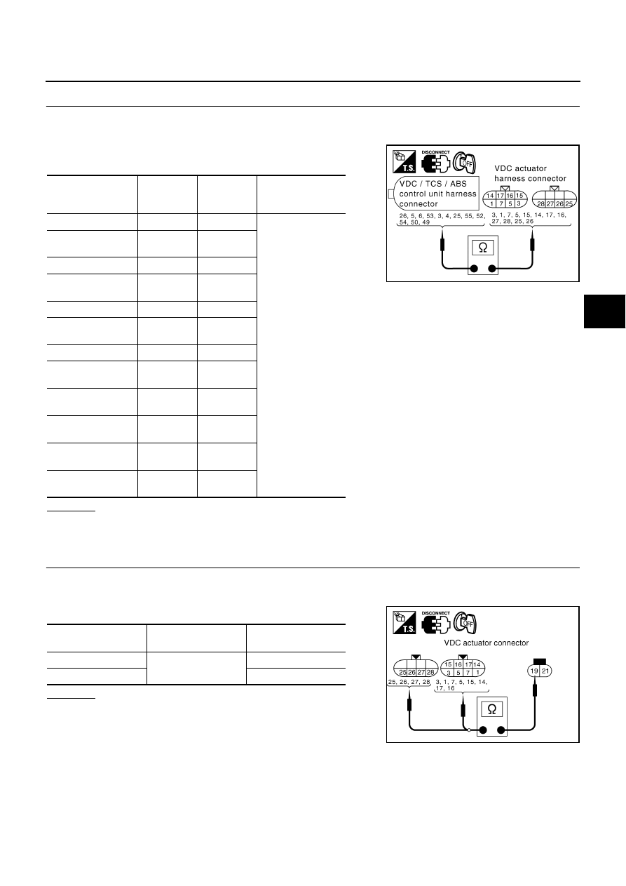
Disconnect VDC actuator connector E21,E22 and VDC/TCS/ABS control unit connector.
3.
Check continuity between VDC/TCS/ABS control unit harness
connector E218 and VDC actuator harness connector E21,E22.
OK or NG
OK
>> GO TO 4.
NG
>> Open or short in harness between VDC/TCS/ABS control unit and VDC actuator
4.
CHECK SOLENOID AND VDC SWITCHING VALVE INPUT SIGNAL
1.
Turn ignition switch “OFF”.
2.
Disconnect VDC actuator connector.
3.
Check resistance of VDC actuator solenoid.
OK or NG
OK
>> Perform VDC/TCS/ABS control unit self-diagnosis
again.
NO
>> Replace VDC actuator assembly.
Item
VDC/TCS/
ABS control
unit
VDC actua-
tor
Continuity
FR LH IN ABS SOL
5
1
Continuity should
exist.
FR LH OUT ABS
SOL
3
14
RR RH IN ABS SOL
6
7
RR RH OUT ABS
SOL
4
17
FR RH IN ABS SOL
26
3
FR RH OUT ABS
SOL
55
15
RR LH IN ABS SOL
53
5
RR LH OUT ABS
SOL
25
16
PRIMARY SIDE
USV CIRCUIT
49
26
SECONDARY SIDE
USV CIRCUIT
50
25
PRIMARY SIDE
HSV CIRCUIT
54
28
SECONDARY SIDE
HSV CIRCUIT
52
27
SFIA2365E
VDC actuator connec-
tor
VDC actuator connec-
tor
Resistance value
1, 3, 5, 7, 25, 26
19
6.0 - 11
Ω
14, 15, 16, 17, 27, 28
3.0 - 5.0
Ω
SFIA2317E