Infiniti Q45. Manual - part 237


  Index      Infiniti     Infiniti Q45 - service repair manual 2006 year


Search            copyright infringement  


Content   ..  235  236  237  238   ..


Infiniti Q45. Manual - part 237


IVIS (INFINITI VEHICLE IMMOBILIZER SYSTEM-NATS)

BL-217

C

D

E

F

G

H

J

K

L

M

A

B

BL

6. 

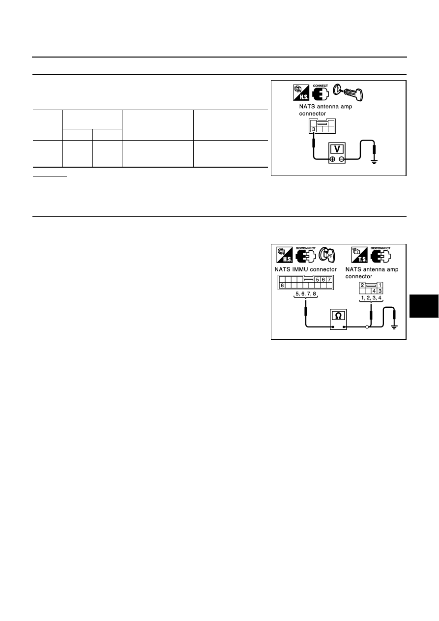
CHECK NATS ANTENNA AMP. CIRCUIT 4

Insert the electronic key into the ignition key cylinder, and immedi-
ately check voltage between NATS antenna amp. connector and
ground.

OK or NG

OK

>> Replace NATS antenna amp.: Reference part E.

NG

>> GO TO 7.

7. 

CHECK NATS ANTENNA AMP. CIRCUIT 5

1.

Turn ignition switch OFF.

2.

Disconnect NATS IMMU and NATS antenna amp. connector.

3.

Check continuity between NATS IMMU connector M32 terminals
5, 6, 7, 8 and NATS antenna amp. connector M65 terminals 1, 2,
3, 4.

4.

Check continuity between NATS IMMU connector M32 terminals
5,  6,  7,  8 and ground.

OK or NG

OK

>> Replace NATS IMMU: Reference part A.

NG

>> Check harness for open or short between NATS IMMU and NATS antenna amp.: Reference parts

E1, 2, 3, 4

Con-

nector

Terminal 

(Wire color)

Condition

Voltage (V)

(Approx.)

(+)

(-)

M65

3 (Y/G)

Ground

Insert electronic key 
into ignition key cylin-
der.

 Pointer of tester should 

move.

PIIA3128E

 5 (R) - 1 (R)

: Continuity should exist.

 6 (Y) - 2 (Y)

: Continuity should exist.

 7 (Y/G) - 3 (Y/G)

: Continuity should exist.

 8 (B/R) - 4 (B/R)

: Continuity should exist.

 5 (R) - Ground

: Continuity should not exist.

 6 (Y) - Ground

: Continuity should not exist.

 7 (Y/G) - Ground

: Continuity should not exist.

 8 (B/R) - Ground

: Continuity should not exist.

PIIA3129E

BL-218

IVIS (INFINITI VEHICLE IMMOBILIZER SYSTEM-NATS)

Removal and Installation NATS Antenna Amp.

NIS000XZ

REMOVAL

1.

Remove the Cluster lid D. Refer to 

IP-12, "(C) Cluster Lid D"

 .

2.

Remove the Knee protector lower. Refer to 

IP-10, "INSTRUMENT PANEL ASSEMBLY"

 .

3.

Remove the Instrument lower driver panel. Refer to 

IP-16, "(V) Instrument Lower Driver Panel"

 .

4.

Remove the Instrument panel bracket. Refer to

IP-10, "INSTRUMENT PANEL ASSEMBLY"

 .

5.

Remove the mounting screw, harness connector and remove
NATS antenna amp.

INSTALLATION

Install in the reverse order of removal.

PIIA4165E

HOMELINK UNIVERSAL TRANSCEIVER

BL-219

C

D

E

F

G

H

J

K

L

M

A

B

BL

HOMELINK UNIVERSAL TRANSCEIVER

PFP:96401

Wiring Diagram – TRNSCV –

NIS000Y0

TIWM0691E

BL-220

HOMELINK UNIVERSAL TRANSCEIVER

Trouble Diagnoses

NIS000Y1

DIAGNOSTIC PROCEDURE
SYMPTOM: Transmitter Does Not Activate Receiver.

Before conducting the procedure given below, make sure that system receiver (garage door opener, etc.)
operates with original, hand-held transmitter. If NG, receiver or hand-held transmitter is malfunctioning, not
vehicle related.

1. 

CHECK ILLUMINATION

Turn ignition switch “OFF”.

Does red light (LED) of transmitter illuminate when any button is
pressed?

YES or NO

YES

>> GO TO 2.

NO

>> GO TO 3.

2. 

TRANSMITTER CHECK

Check transmitter with Tool*.
*: For details, refer to Technical Service Bulletin.

OK or NG

OK

>> Receiver or handheld transmitter malfunction, not vehicle related.

NG

>> Replace transmitter with sun visor assembly.

3. 

CHECK BATTERY POWER SUPPLY

1.

Disconnect transmitter connector.

2.

Turn ignition switch “OFF”.

3.

Check voltage between transmitter harness connector R5 terminal 1 and ground.

OK or NG

OK

>> GO TO 4.

NG

>>

Check 10A fuse [No. 8 located in the fuse block (J/B)
No.1]

Harness for open or short between fuse and transmit-
ter

SEL442U

1 (LG) – Ground

: Battery voltage.

PIIB2120E


Content   ..  235  236  237  238   ..