Infiniti Q45. Manual - part 227


  Index      Infiniti     Infiniti Q45 - service repair manual 2006 year


Search            copyright infringement  


Content   ..  225  226  227  228   ..


Infiniti Q45. Manual - part 227


VEHICLE SECURITY (THEFT WARNING) SYSTEM

BL-177

C

D

E

F

G

H

J

K

L

M

A

B

BL

1 – 4 CHECK TRUNK LID LOCK SWITCH

1. 

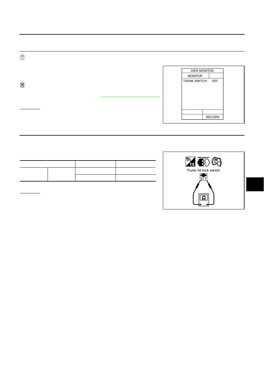
CHECK TRUNK ROOM LAMP SWITCH INPUT SIGNAL

 With CONSULT-II

Check “TRUNK SWITCH” in “DATA MONITOR” mode with CONSULT

II.

 Without CONSULT-II

Check trunk lid lock switch in Switch monitor mode.
Refer to Remote keyless entry system 

BL-82, "SWITCH MONITOR"

.

OK or NG

OK

>> Trunk lid lock switch is OK.

NG

>> GO TO 2.

2. 

CHECK TRUNK LID LOCK SWITCH

1.

Turn ignition switch OFF.

2.

Disconnect trunk lid lock switch connector.

3.

Check continuity between trunk lid lock switch terminals 1and 2.

(): with auto trunk

OK or NG

OK

>> Check the following. Repair or replace following item, 

when there is a malfunction.

Trunk lid lock switch ground circuit

Harness for open or short between trunk lid lock switch and BCM

NG

>> Replace trunk lid lock switch.

When trunk lid is open

: TRUNK SW ON

When trunk lid is closed

: TRUNK SW OFF

PIIA0345E

Terminal

Condition of trunk lid

Continuity

1

2

Closed

No

Open

Yes

PIIA3073E

BL-178

VEHICLE SECURITY (THEFT WARNING) SYSTEM

Diagnostic Procedure 2

NIS000WZ

CHECK SECURITY INDICATOR LAMP

1. 

INDICATOR LAMP ACTIVE TEST

With CONSULT-II

Check “INDICATOR LAMP” in “ACTIVE TEST” mode with CONSULT-II.

NOTE:
If CONSULT-II is not available, skip this procedure and go to the
next procedure.

OK or NG

OK

>> Security indicator lamp is OK.

NG

>> GO TO 2.

2. 

CHECK INDICATOR LAMP

1.

Turn ignition switch OFF.

2.

Check indicator lamp condition.

OK or NG

OK

>> GO TO 3.

NG

>> Replace indicator lamp.

3. 

CHECK POWER SUPPLY CIRCUIT FOR INDICATOR LAMP

1.

Disconnect multifunction switch (security indicator lamp) connector.

2.

Check voltage between multifunction switch (security indicator lamp) connector M83 terminal 20 and
ground.

OK or NG

OK

>> Check harness for open or short between multifunction

switch (security indicator lamp) and BCM.

NG

>> Check the following.

10A fuse [No. 6, located in fuse block (J/B) No. 1]

Harness for open or short between multifunction
switch (security indicator lamp) and fuse.

Perform operation shown on display.
Indicator lamp should illuminate.

PIIA0347E

20 (Y/G) – Ground

: Battery voltage.

PIIA3134E

VEHICLE SECURITY (THEFT WARNING) SYSTEM

BL-179

C

D

E

F

G

H

J

K

L

M

A

B

BL

Diagnostic Procedure 3

NIS000X0

CHECK DOOR UNLOCK SENSOR

1. 

CHECK DOOR UNLOCK SENSOR INPUT SIGNAL

 With CONSULT-II

Check door unlock sensor “LOCK SIG” in “DATA MONITOR” mode with CONSULT-II.

 Without CONSULT-II

Check door lock knob operation in Switch monitor mode.
Refer to Remote keyless entry system 

BL-82, "SWITCH MONITOR"

.

OK or NG

OK

>> Door unlock sensor is OK.

NG

>> GO TO 2. (Diagnose the malfunctioning door parts in

accordance with the following charts.)

2. 

CHECK DOOR UNLOCK SENSOR INPUT SIGNAL

1.

Turn ignition switch “OFF”.

2.

Disconnect door lock actuator connector.

3.

Check voltage between each door control unit connector and ground.

OK or NG

OK

>> GO TO 3.

NG

>> Replace malfunctioning door control unit.

When door is locked

: LOCK SIG  LOCK

When door is unlocked

: LOCK SIG UNLK

PIIA2803E

Door control unit connector

Terminal (Wire color)

Voltage (V)

(Approx.)

(+)

(-)

Front door

 Driver side: D8

6 (G/Y) 

Ground

5

Passenger side: D38

13 (G/Y)

Rear door

LH: D58

RH: D78

PIIB0179E

BL-180

VEHICLE SECURITY (THEFT WARNING) SYSTEM

3. 

CHECK DOOR UNLOCK SENSOR SIGNAL CIRCUIT

1.

Disconnect door control unit connector.

2.

Check continuity between door control unit and door lock actuator (door unlock sensor) conectors.

3.

Check continuity between door control unit and ground.

OK or NG

OK

>> GO TO 4.

NG

>> Repair or replace harness.

4. 

CHECK DOOR UNLOCK SENSOR GROUND CIRCUIT

1.

Turn ignition switch “OFF”.

2.

Disconnect door lock actuator connector.

3.

Check continuity between each door control unit and ground.

OK or NG

OK

>> Replace door lock actuator (door unlock sensor).

NG

>> Repair or replace harness.

 Connector

Terminal 

(wire color)

Connector

Terminal 

(Wire color)

Continuity

Driver side: 
D8

 6 (G/Y)

D11

2 (G/Y)

Yes

Passenger 
side: D38

13 (G/Y)

D41

Rear LH: 
D58

D61

Rear RH: 
D78

D81

 Connector

Terminal (wire color)

Continuity

Driver side: D8

 6 (G/Y)

Ground

No

Passenger side: D38

13 (G/Y)

Rear LH: D58

Rear RH: D78

PIIA2857E

PIIB0180E

 Connector

Terminal (wire color)

Continuity

Driver side: D11

 4 (B)

Ground

Yes

Passenger side: D41

Rear LH: D61

Rear RH: D81

PIIA2859E


Content   ..  225  226  227  228   ..