Infiniti Q45. Manual - part 224


  Index      Infiniti     Infiniti Q45 - service repair manual 2006 year


Search            copyright infringement  


Content   ..  222  223  224  225   ..


Infiniti Q45. Manual - part 224


VEHICLE SECURITY (THEFT WARNING) SYSTEM

BL-165

C

D

E

F

G

H

J

K

L

M

A

B

BL

TIWM1557E
BL-166

VEHICLE SECURITY (THEFT WARNING) SYSTEM

TIWM1558E

VEHICLE SECURITY (THEFT WARNING) SYSTEM

BL-167

C

D

E

F

G

H

J

K

L

M

A

B

BL

Terminal and Reference Value for BCM

NIS000WR

TER-

MINAL

WIRE 

COLOR

ITEM

Signal 

input/

output

CONDITION

VOLTAGE (V)

(Approx.)

5

R/Y

Headlamp relay

Input

Lighting switch is turned OFF posi-
tion

Battery voltage

Lighting switch is turned ON position

0

27

BR/W

Remote keyless entry 
receiver
(Pulse)

Input/

output

Stand-by

Press any of the electronic key 
switches

28

L

Remote keyless entry 
receiver
(Power supply)

Input/

output

Stand-by

Press any of the electronic key 
switches

33

W

Rear LH door switch

Input

Door open (ON) 

→

 close (OFF)

0 

→

 Battery voltage

37

W/G

Passenger door switch

Input

Door open (ON) 

→

 close (OFF)

0 

→

 Battery voltage

44

Y

Remote keyless entry 
receiver
(Ground)

—

—

0

56

B

Ground

—

—

0

60

L/OR

Ignition switch (ACC)

Input

Ignition switch (ACC or ON position)

Battery voltage

65

G

Multifunction switch (secu-
rity indicator lamp)

Input

Goes OFF 

→

 Illuminates (every 2.4 

seconds)

Battery voltage 

→

 0

67

G/W

Data line A-3

Input/

output

—

—

68

W/B

Ignition switch (ON)

Input

Ignition switch (ON or START posi-
tion)

Battery voltage

105

Y/L

Power source (Fuse)

Input

—

Battery voltage

113

B

Ground

—

—

0

122

LG/B

Hood switch

Input

Hood open (ON) 

→

 close (OFF)

0 

→

 Battery voltage

127

G/W

Horn relay

Input

When panic alarm is operated using 
electronic key. (ON 

→

 OFF)

0 

→

 Battery voltage 

OCC3879D

OCC3880D

OCC3881D

OCC3880D

BL-168

VEHICLE SECURITY (THEFT WARNING) SYSTEM

Terminal and Reference Value for Driver Door Control Unit (LCU01)

NIS000WS

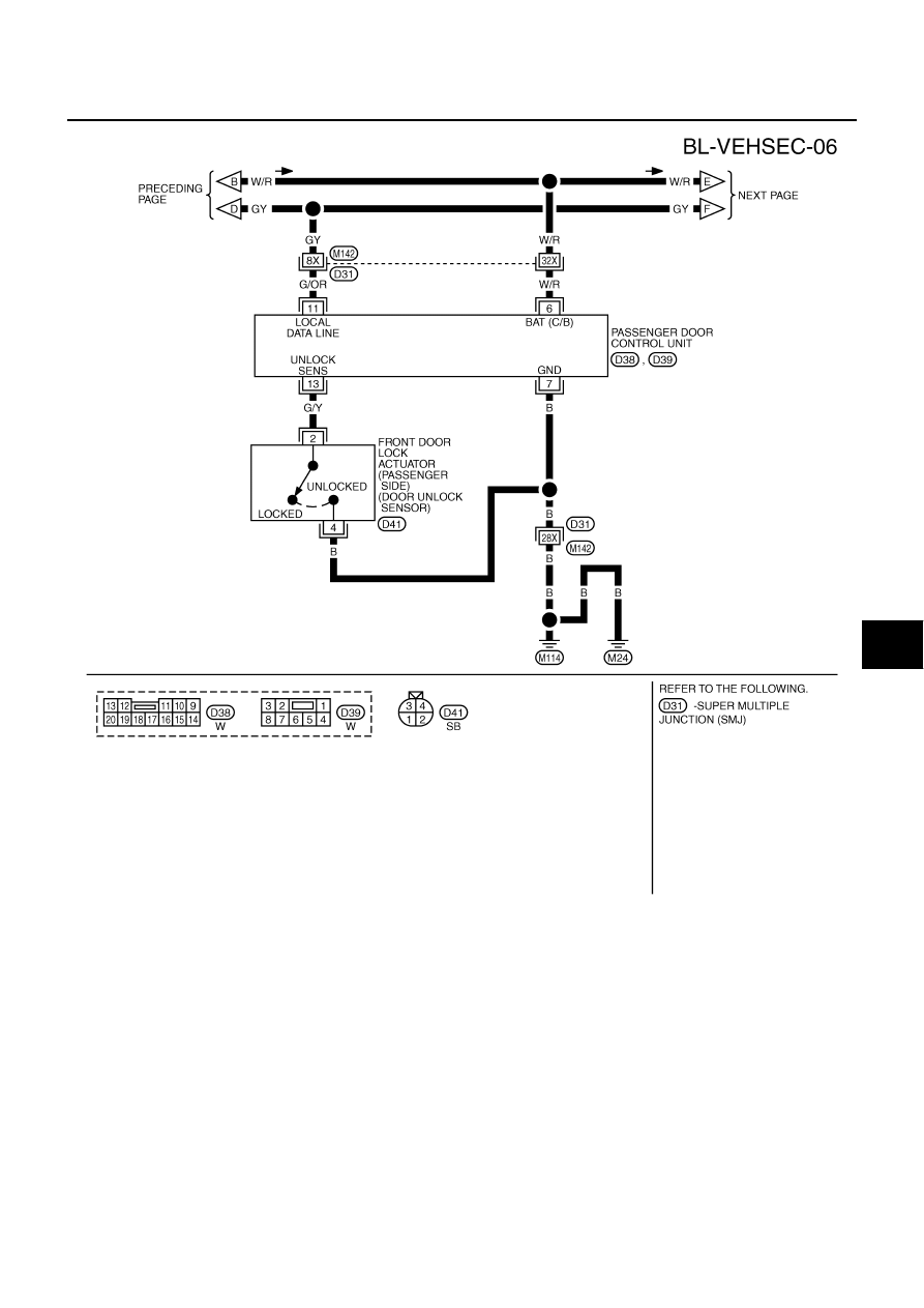
Terminal and Reference Value Passenger And Rear LH, RH Door Control Unit

NIS000WT

( ): Wire color for rear LH, RH door control unit.

142

W/R

Driver door switch

Input

Door open (ON) 

→

 close (OFF)

0 

→

 Battery voltage

143

W/L

Rear RH door switch

Input

Door open (ON) 

→

 close (OFF)

0 

→

 Battery voltage

145

LG

Trunk lid key cylinder switch 
(unlock switch)

Input

Trunk lid switch “N” position 

→


between full stroke and “N” position

5 

→

 0

146

P

Trunk lid lock switch

Input

Trunk lid open (ON) 

→

 close (OFF)

0 

→

 Battery voltage

TER-

MINAL

WIRE 

COLOR

ITEM

Signal 

input/

output

CONDITION

VOLTAGE (V)

(Approx.)

TERMI-

NAL

WIRE 

COLOR

ITEM

Signal 

input/

output

CONDITION

VOLTAGE (V)

(Approx.)

5

G/OR

Local communication line

Input/

output

—

6

G/Y

Door unlock sensor

Output

OFF (Locked) 

→

 ON (unlocked)

5 

→

 0

8

G/W

Data line A-3

Input/

output

—

—

9

PU/W

Door key cylinder switch

Input

OFF (Neutral) 

→

 ON (Unlocked)

5 

→

 0

10

GY

Door key cylinder lock 
switch

Input

OFF (Neutral) 

→

 ON (Locked)

5 

→

 0

14

Y/G

Power source (C/B)

Input

—

Battery voltage

15

B

Ground

—

—

0

SIIA0591J

TERMI-

NAL

WIRE 

COLOR

ITEM

Signal 

input/

output

CONDITION

VOLTAGE (V)

(Approx.)

6

W/R

(Y/B)

Power source (C/B)

Input

—

Battery voltage

7

B

Ground

—

—

0

11

G/OR

Local communication line

Input/

output

—

13

G/Y

Door unlock sensor

Output

OFF (Locked) 

→

 ON (Unlocked)

5 

→

 0

SIIA0591J


Content   ..  222  223  224  225   ..