Infiniti Q45. Manual - part 191


  Index      Infiniti     Infiniti Q45 - service repair manual 2006 year


Search            copyright infringement  


Content   ..  189  190  191  192   ..


Infiniti Q45. Manual - part 191


POWER DOOR LOCK SYSTEM

BL-33

C

D

E

F

G

H

J

K

L

M

A

B

BL

Preliminary Check

NIS000U0

POWER SUPPLY AND GROUND CIRCUIT INSPECTION

1. 

FUSE INSPECTION

Check if any of the following fuses are blown.

Refer to 

BL-23, "Wiring Diagram — D/LOCK —"

 .

Refer to 

BL-23, "Wiring Diagram — D/LOCK —"

 .

OK or NG

OK

>> GO TO 2.

NG

>> If fuse is blown, be sure to eliminate cause of malfunction before installing new fuse, refer to 

PG-

2, "POWER SUPPLY ROUTING"

 .

2. 

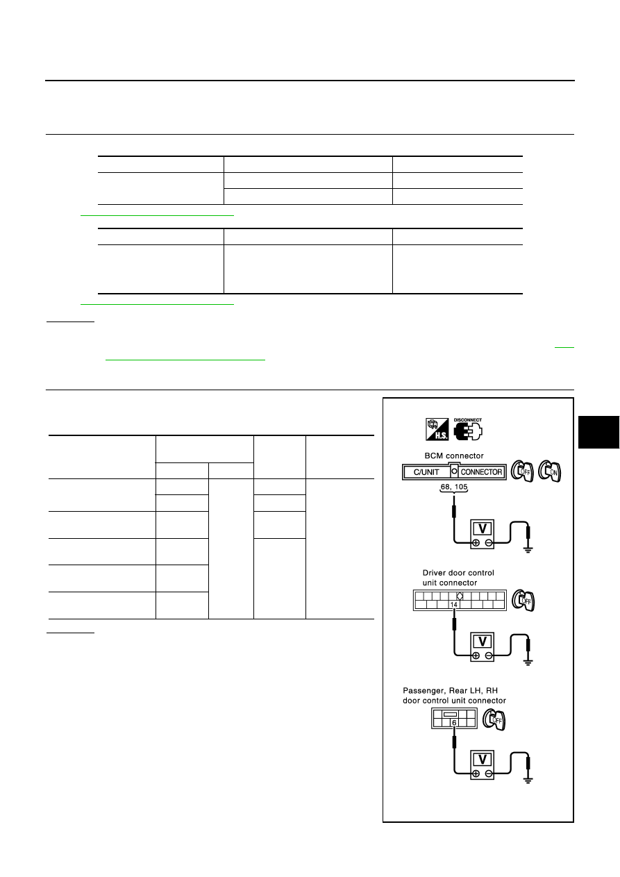
POWER SUPPLY CIRCUIT INSPECTION

Remove the connectors of BCM and driver door LCU or passenger,
rear LH, RH door control units, measure the voltage between the fol-
lowing terminals of connector and ground.

OK or NG

OK

>> GO TO 3.

NG

>> Check harness for open or short.

Unit

Power source

Fuse No.

BCM

Battery power supply

3 (10A)

IGN power supply

1 (10A)

Unit

Power source

Fusible link letter

Driver door control unit
Passenger door control unit
Rear LH door  control unit
Rear RH door control unit

Battery power supply

H (40A)

Unit

(Connector)

Terminals

(wire color)

Ignition

switch

condition

Voltage (V)

(Approx.)

(+)

(–)

BCM (M4)

105 (Y/L)

Ground

OFF

Battery voltage

68 (W/B)

ON

Driver door control unit 
(D8)

14 (Y/G)

OFF

Passenger door control 
unit (D39)

6 (W/R)

OFF

Rear LH door control unit 
(D59)

6 (Y/B)

Rear RH door control 
unit (D79)

6 (Y/B)

PIIA4454E

BL-34

POWER DOOR LOCK SYSTEM

3. 

GROUND CIRCUIT INSPECTION

Check the continuity between the following terminals connector for
BCM, driver door LCU,   passenger or rear RH, LH door control units
and ground.

OK or NG

OK

>> Power supply and ground circuit is OK.

NG

>> Repair or replace harness.

CONSULT-II Function

NIS000U1

CONSULT-II executes the following functions by combining data reception and command transmission via the
communication line from BCM. IVMS communication inspection, work support (only function setting of seats
and steering wheel), self-diagnosis, data monitor, and active test display.

DIAGNOSTIC ITEMS DESCRIPTION

Unit

(Connector)

Terminals

(wire color)

Continuity

(+)

(–)

BCM (M4)

56 (B)

Ground

Yes

113 (B)

Driver door control unit 
(D8)

15 (B)

Passenger door control 
unit (D39)

7 (B)

Rear LH door control unit 
(D59)

Rear RH door control unit 
(D79)

PIIA4473E

IVMS diagnosis 

position

 Diagnosis mode

Description

IVMS-
COMM CHECK

IVMS-
COMM DIAGNOSIS

Diagnosis of continuity in the communication line(s), and of the function of the 
IVMS-communication interface between the body control module and the 
local control units, accomplished by transmitting a signal from the body con-
trol module to the local control units.

WAKE-UP DIAGNOSIS

Diagnosis of the“ wake-up” function of local control units by having a techni-
cian input the switch data into the local control unit that is in the temporary 
“sleep” condition.

POWER DOOR LOCK SYSTEM

BL-35

C

D

E

F

G

H

J

K

L

M

A

B

BL

CONSULT-II BASIC OPERATION PROCEDURE

1.

With the ignition switch OFF, connect “CONSULT-II” and “CON-
SULT-II CONVERTER” to the data link connector, and turn the
ignition switch ON.

2.

Touch "START (NISSAN BASED VHCL)".

3.

Touch "IVMS".
If “IVMS” is not indicated, go to

GI-37, "CONSULT-II Data Link

Connector (DLC) Circuit"

 .

Each system 
inspection

Work support

Changes the setting for each function.

Self-diagnosis results

Carries out self-diagnosis.

Data monitor

Displays data relative to the body control module (BCM) input signals and var-
ious control related data for each system.

Active test

Turns on/off actuators, relay and according to the commands transmitted by 
the CONSULT-II unit.

BCM PART NUMBER

Displays BCM part No.

IVMS diagnosis 

position

 Diagnosis mode

Description

SHIA0179E

BCIA0029E

BCIA0030E

BL-36

POWER DOOR LOCK SYSTEM

4.

Check the model specification, touch either "WITH SUNROOF"
or "WITHOUT SUNROOF".

5.

Touch "OK". If the selection is wrong, touch "CANCEL".

6.

Select the desired part to be diagnosed on the "SELECT TEST ITEM" screen.

IVMS COMMUNICATION INSPECTION

IVMS contains the IVMS communication diagnosis and wake-up diagnosis.

IVMS Communication Diagnosis.

IVMS communication diagnosis consists of the communication diagnosis, sleep diagnosis, and inactive
communication diagnosis between BCM and each local unit (LCU), and display the results on the CON-
SULT-II screen.
NOTE:
Sleep is a power saving function when a vehicle is stationary (all BCM related electrical equipment: OFF,
and the timer: OFF).

The function also stores the communication malfunction records and inactive communication records, and
displays the data on the CONSULT-II screen (Malfunction record diagnosis)

*: malfunctioning item record

Operation Procedure

1.

Touch "IVMS-COMM CHECK" on "SELECT TEST ITEM".

2.

Touch "IVMS-COMM DIAGNOSIS" on "SELECT DIAG ITEM" screen.

3.

Touch "START" on "IVMS-COMM DIAGNOSIS" screen to start the diagnosis.

4.

After the diagnosis is completed, the malfunctioning system is displayed.

5.

When the malfunctioning items are displayed, touch "PRINT" to record.

6.

Touch "ERASE".

7.

Perform the communication inspection again to make sure that any malfunctioning item is displayed.

8.

Check the displayed items. 

Wake-Up Diagnosis

The wake-up diagnosis is carried out when BCM detects the wake-up signal from each local unit (LCU). When
the switch shown on the screen is operated as instructed, each local control unit (LCU) outputs the wake-up

PIIA0184E

Malfunction description

CONSULT-II

display item

Description

Communication malfunction

COMM DATA

Communicating with each LCU is judged sound when the communication is 
normally completed and the transmitted data and received data are identically 
the same. In other cases, it is judged malfunctioning. If the communication is 
inactive, no diagnosis result is displayed.

Inactive communication

NO RESPONSE

Communicating with each LCU is judged sound when at least one time commu-
nication is normally completed within three trials. In other cases, it is judged 
malfunctioning.

Sleep malfunction

SLEEP

Make sure that each LCU enters sleep mode.

Communication malfunction*

PAST COMM
DATA

The records when communication signal malfunctions were continuously 
detected while the communication was normal are displayed. Or the records 
when a malfunction is detected during the past sleep mode are displayed.

Inactive communication*

PAST NO
RESPONSE

The records when inactive communications were continuously detected while 
the communication was normal are displayed.


Content   ..  189  190  191  192   ..