Infiniti Q45. Manual - part 121


  Index      Infiniti     Infiniti Q45 - service repair manual 2006 year


Search            copyright infringement  


Content   ..  119  120  121  122   ..


Infiniti Q45. Manual - part 121


TROUBLE DIAGNOSIS

ATC-79

C

D

E

F

G

H

I

K

L

M

A

B

ATC

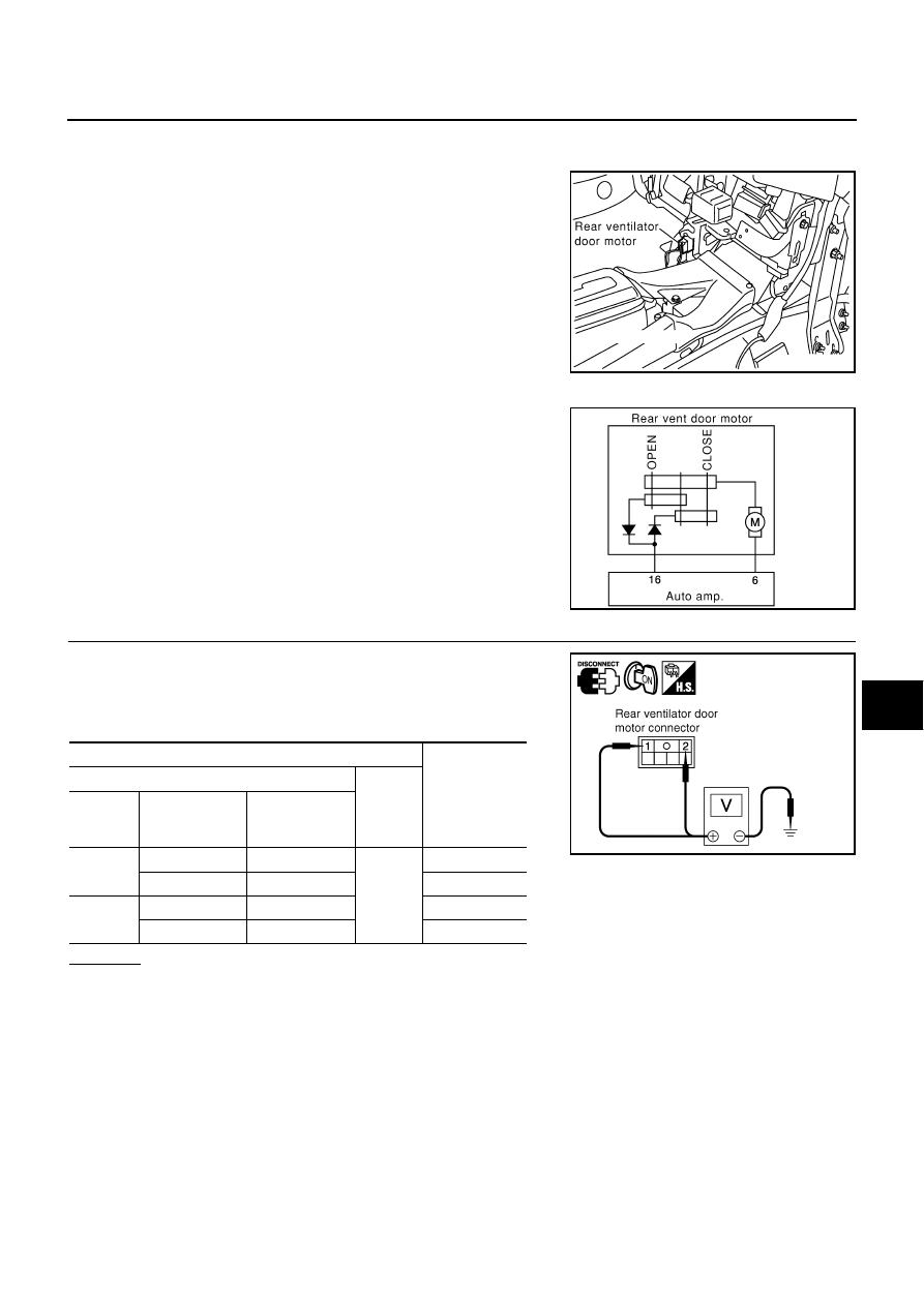
Rear Ventilator Door Motor Circuit

NJS0008J

COMPONENT DESCRIPTION

Rear ventilator door motor is attached to the rear ventilator duct No.
1. Rear ventilator door is opened or closed by rear ventilator door
motor.

DIAGNOSIS PROCEDURE FOR REAR VENTILATOR DOOR MOTOR

SYMPTOM: Rear ventilator door motor does not operate.

1. 

CHECK FOR AUTO AMP. OUTPUT

1.

Disconnect rear ventilator door motor connector.

2.

Set up code No. 41 and 42 in self-diagnosis STEP-4.

3.

Check voltage between rear ventilator door motor harness con-
nector M93 terminals 1, 2 and ground.

OK or NG

OK

>> Replace rear ventilator door motor.

NG

>> GO TO 2.

RJIA0289E

RJIA0290E

Terminals

Voltage

(+)

(

)

Code No.

Rear ventilator 

door motor con-

nector

Terminal No. 

41

M93

1

Ground

Approx. 12 V

M93

2 Approx. 

V

42

M93

1

Approx. 0 V

M93

2

Approx. 12 V

RJIA3028E

ATC-80

TROUBLE DIAGNOSIS

2. 

CHECK CIRCUIT CONTINUITY BETWEEN REAR VENTILATOR DOOR MOTOR AND AUTO AMP.

1.

Turn ignition switch OFF.

2.

Disconnect auto amp. connector.

3.

Check continuity between rear ventilator door motor harness
connector M93 terminals 1, 2 and auto amp. harness connector
M119 terminals 6, 16.

OK or NG

OK

>> Replace auto amp.

NG

>> GO TO 

ATC-80, "DIAGNOSIS PROCEDURE FOR

REAR CONTROL SWITCH"

 .

Rear Control Switch Circuit

NJS0008K

DIAGNOSIS PROCEDURE FOR REAR CONTROL SWITCH

SYMPTOM: Rear control switch does not operate.

1. 

CHECK MULTIPLEX COMMUNICATION ERROR

1.

Set in self-diagnosis STEP-5. Refer to 

ATC-54, "FUNCTION CONFIRMATION PROCEDURE"

 .

2.

Press intake switch.

3.

Check multiplex communication error between rear control switch and auto amp.

OK or NG

OK

>> GO TO 

AV-47, "Rear Control Switch Does Not Operate"

 .

NG

>> GO TO 

ATC-123, "DIAGNOSIS PROCEDURE FOR MULTIPLEX COMMUNICATION CIRCUIT

(REAR CONTROL SWITCH)"

 .

Rear Control Cancel Switch

NJS000CK

DIAGNOSIS PROCEDURE FOR REAR CONTROL CANCEL SWITCH

SYMPTOM: Rear control switch does not operate.
Refer to 

AV-47, "Rear Control Switch Does Not Operate"

 .

1 – 6

: Continuity should exist.

2 – 16

: Continuity should exist.

RJIA3029E

TROUBLE DIAGNOSIS

ATC-81

C

D

E

F

G

H

I

K

L

M

A

B

ATC

Blower Motor Circuit

NJS0008L

SYMPTOM: Blower motor operation is malfunctioning.

INSPECTION FLOW

SYSTEM DESCRIPTION
Component Parts

Fan speed control system components are:

Auto amp.

*1

ATC-62, "Operational Check"

*2

ATC-54, "FUNCTION CONFIRMA-
TION PROCEDURE"

, see No. 1.

*3

ATC-54, "FUNCTION CONFIRMA-
TION PROCEDURE"

, see No. 5.

*4

ATC-54, "FUNCTION CONFIRMA-
TION PROCEDURE"

, see No. 7.

*5

ATC-54, "FUNCTION CONFIRMA-
TION PROCEDURE"

, see No. 14.

*6

ATC-81, "Blower Motor Circuit"

*7

ATC-110, "Ambient Sensor Circuit"

 *8

ATC-112, "In-Vehicle Sensor Circuit"

*9

ATC-115, "Sunload Sensor Circuit"

*10

ATC-118, "Intake Sensor Circuit"

*11

ATC-35, "SYMPTOM TABLE"

SJIA1136E

ATC-82

TROUBLE DIAGNOSIS

A/C LAN system (PBR built-in mode door motor, air mix door motor and intake door motor)

In-vehicle sensor

Ambient sensor

Sunload sensor

Intake sensor

System Operation

Automatic Mode

In the automatic mode, the blower motor speed is calculated by the auto amp. based on the input from the
PBR, in-vehicle sensor, sunload sensor, intake sensor and ambient sensor.
When the air flow is increased, the duty ratio of the blower fan motor’s drive signal is changed at 8%/sec. to
prevent a sudden increase in air flow.
In addition to manual air flow control and the usual automatic air flow control, starting air flow control, low
water temperature starting control and high passenger compartment temperature starting control are avail-
able.
When the audio-recognition signal is input to the auto amp., the maximum fan speed is limited to the 3rd step.
(Except DEF).

Starting Fan Speed Control

Start up from COLD SOAK Condition (Automatic mode)
In a cold start up condition where the engine coolant temperature is below 56

°

C (133

°

F), the blower will not

operate for a short period of time (up to 150 seconds). The exact start delay time varies depending on the
ambient and engine coolant temperature.
In the most extreme case (very low ambient) the blower starting delay will be 150 seconds as described
above. After this delay, the blower will operate at low speed until the engine coolant temperature rises above
56

°

C (133

°

F), at which time the blower speed will increase to the objective speed.

Start up from usual or HOT SOAK Condition (Automatic mode)
The blower will begin operation momentarily after the AUTO switch is pushed. The blower speed will gradually
rise to the objective speed over a time period of 3 seconds or less (actual time depends on the objective
blower speed).

RJIA1293E


Content   ..  119  120  121  122   ..