Infiniti Q45. Manual - part 108
AIR CONDITIONER CONTROL
ATC-27
C
D
E
F
G
H
I
K
L
M
A
B
ATC
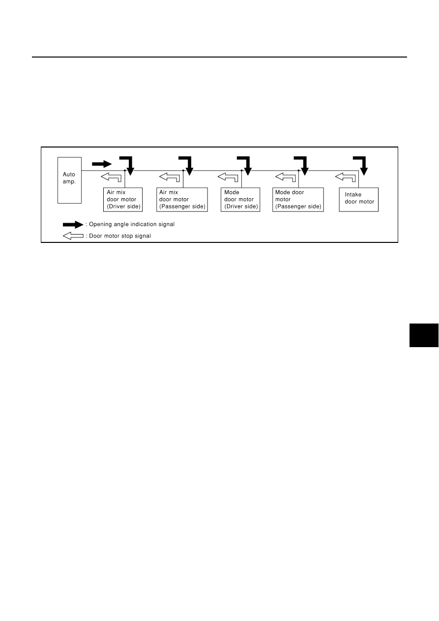
OPERATION
The auto amp. receives data from each of the sensors. The auto amp. sends mode door, air mix door and
intake door opening angle data to the mode door motor LCU, air mix door motor LCU and intake door motor
LCU.
The mode door motor, air mix door motor and intake door motor read their respective signals according to the
address signal. Opening angle indication signals received from the auto amp. and each of the motor position
sensors is compared by the LCUs in each door motor with the existing decision and opening angles. Subse-
quently, HOT/COLD, DEF/VENT and FRESH/RECIRCULATION operation is selected. The new selection data
is returned to the auto amp.
TRANSMISSION DATA AND TRANSMISSION ORDER
Auto amp. data is transmitted consecutively to each of the door motor following the form shown in figure
below.
Start:
Initial compulsory signal is sent to each of the door motor.
Address:
Data sent from the auto amp. are selected according to data-based decisions made by the air mix door motor,
mode door motor and intake door motor.
If the addresses are identical, the opening angle data and error check signals are received by the door motor
LCUs. The LCUs then make the appropriate error decision. If the opening angle data have no error, door con-
trol begins.
If an error exists, the received data are rejected and corrected data received. Finally, door control is based
upon the corrected opening angle data.
Opening angle:
Data that show the indicated door opening angle of each door motor.
Error check:
Procedure by which sent and received data are checked for errors. Error data are then compiled. The error
check prevents corrupted data from being used by the air mix door motor, mode door motor and intake door
motor. Error data can be related to the following problems.
●
Malfunction electrical frequency
●
Poor electrical connections
●
Signal leakage from transmission lines
●
Signal level fluctuation
RJIA0201E