Infiniti Q45. Manual - part 83


  Index      Infiniti     Infiniti Q45 - service repair manual 2006 year


Search            copyright infringement  


Content   ..  81  82  83  84   ..


Infiniti Q45. Manual - part 83


ON-VEHICLE SERVICE

AT-245

D

E

F

G

H

I

J

K

L

M

A

B

AT

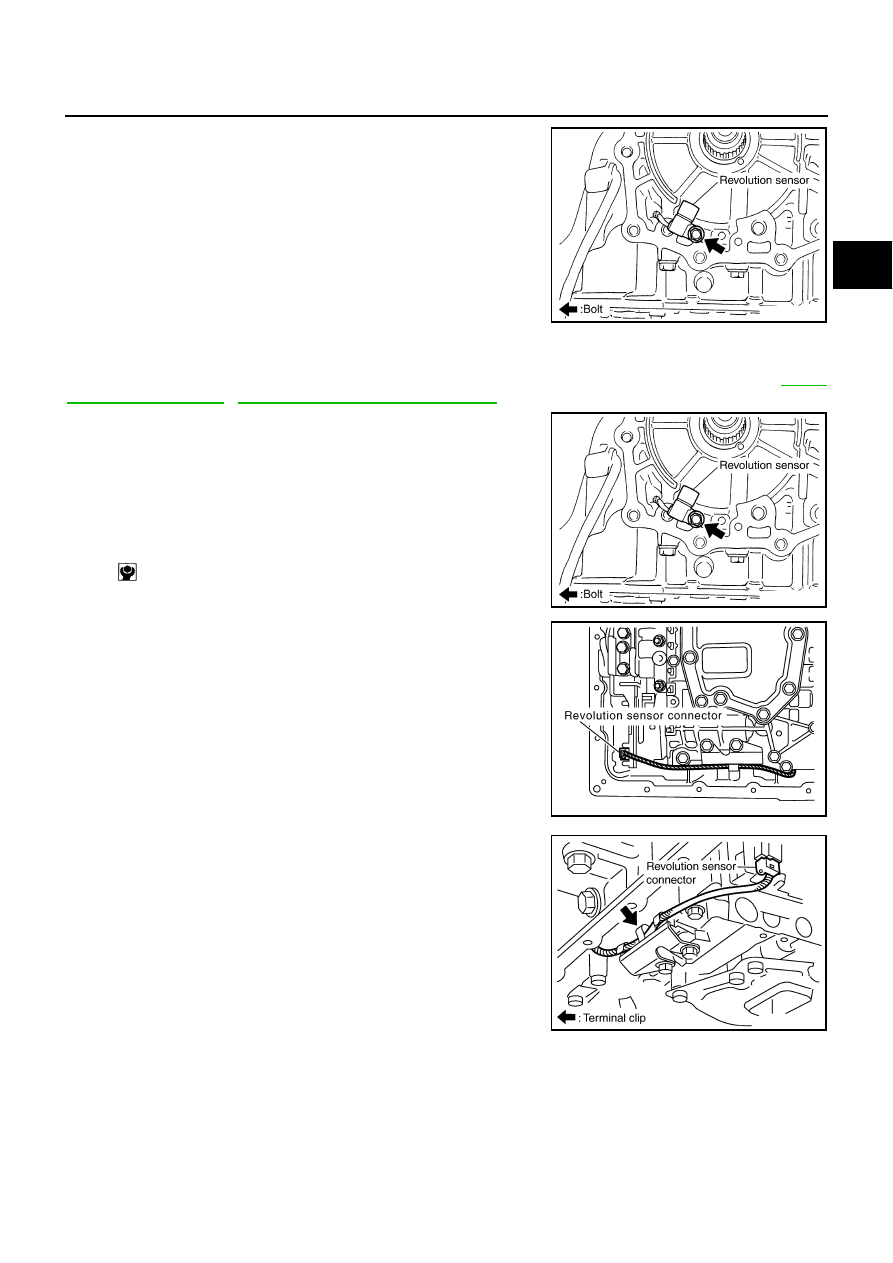
16. Remove revolution sensor from transmission case.

CAUTION:

Do not subject it to impact by dropping or hitting it.

Do not disassemble.

Do not allow metal filings, etc. to get on the sensor's front
edge magnetic area.

Do not place in an area affected by magnetism.

INSTALLATION

CAUTION:

After completing installation, check A/T fluid leakage, A/T fluid level and A/T position. Refer to 

AT-13,

"Checking A/T Fluid"

 , 

AT-218, "Checking of A/T Position"

 .

1.

Install revolution sensor in transmission case.

CAUTION:

Do not subject it to impact by dropping or hitting it.

Do not disassemble.

Do not allow metal filings, etc. to get on the sensor's front
edge magnetic area.

Do not place in an area affected by magnetism.

2.

Connect revolution sensor connector.

3.

Securely fasten revolution sensor harness with clip.

SCIA3997E

: 5.8 N·m (0.59 kg-m, 51 in-lb)

SCIA3997E

SCIA7518E

SCIA7525E

AT-246

ON-VEHICLE SERVICE

4.

Apply recommended sealant (Genuine Anaerobic Liquid Gasket
or equivalent. Refer to 

GI-45, "Recommended Chemical Prod-

ucts and Sealants"

 .) to output shaft & companion flange com-

plement as shown in the figure.

CAUTION:

Completely remove all moisture, oil and old sealant, etc.
from the transmission case and output shaft & companion
flange complement mounting surfaces.

5.

Install output shaft & companion flange complement in A/T
assembly.

CAUTION:

Insert the tip of parking rod between the parking actuator
support when assembling the output shaft companion
flange complement.

6.

Tighten output shaft & companion flange complement mounting
bolts (1) to specified torque.

: Bolt (10)

CAUTION:

Do not reuse self-sealing bolts (2).

7.

Install rear engine mounting insulator. Refer to 

EM-79, "Removal

and Installation"

 .

SCIA5212E

SCIA5688E

Output shaft & companion flange complement 
mounting bolt:

: 52 N·m (5.3 Kg-m, 38 ft-lb)

Self-sealing bolt:

: 61 N·m (6.2 Kg-m, 45 ft-lb)

SCIA6943E

SCIA5686E

ON-VEHICLE SERVICE

AT-247

D

E

F

G

H

I

J

K

L

M

A

B

AT

8.

Install rear member. Refer to 

AT-249, "Removal and Installation"

.

9.

Install oil pan to transmission case.

a.

Install oil pan gasket to oil pan.

CAUTION:

Do not reuse oil pan gasket.

Install it in the direction to align hole positions.

Completely remove all moisture, oil and old gasket, etc. from oil pan mounting surface.

b.

Install oil pan (with oil pan gasket) to transmission case.

CAUTION:

Install it so that drain plug comes to the position as
shown in the figure.

Be careful not to pinch harnesses.

Completely remove all moisture, oil and old gasket, etc.
from oil pan mounting surface.

c.

Tighten oil pan mounting bolts to the specified torque in numeri-
cal order shown in the figure after temporarily tightening them.

CAUTION:

Do not reuse oil pan mounting bolts.

10. Install drain plug to oil pan.

CAUTION:

Do not reuse drain plug gasket.

11. Install control rod. Refer to 

AT-217, "Control Rod Removal and Installation"

 .

12. Install rear propeller shaft. Refer to 

PR-5, "Removal and Installation"

 .

13. Install exhaust front tube and center muffler. Refer to 

EX-3, "Removal and Installation"

 .

14. Pour ATF into A/T assembly. Refer to 

AT-12, "Changing A/T Fluid"

 .

15. Connect the battery cable to the negative terminal.

SCIA5676E

SCIA2308E

: 7.9 N·m (0.81 kg-m, 70 in-lb)

: 34 N·m (3.5 kg-m, 25 ft-lb)

SCIA4113E

AT-248

AIR BREATHER HOSE

AIR BREATHER HOSE

PFP:31098

Removal and Installation

NCS0011C

Refer to the figure below for air breather hose removal and installation procedure.

CAUTION:

When installing an air breather hose, be careful not to be crushed or blocked by folding or bend-
ing the hose.

When inserting a hose to the transmission tube, be sure to insert it fully until its end reaches the
tube bend “R” portion.

SCIA6953E


Content   ..  81  82  83  84   ..