Infiniti Q45. Manual - part 58
DTC P1757 FRONT BRAKE SOLENOID VALVE
AT-145
D
E
F
G
H
I
J
K
L
M
A
B
AT
DTC P1757 FRONT BRAKE SOLENOID VALVE
PFP:31940
Description
NCS000XW
Front brake solenoid valve is controlled by the TCM in response to signals sent from the PNP switch, vehicle
speed sensor and accelerator pedal position sensor (throttle position sensor). Gears will then be shifted to the
optimum position.
CONSULT-II Reference Value
NCS000XX
On Board Diagnosis Logic
NCS000XY
●
This is an OBD-II self-diagnostic item.
●
Diagnostic trouble code “P1757 FR/B SOLENOID/CIRC” with CONSULT-II or 6th judgement flicker with-
out CONSULT-II is detected under the following conditions.
–
When TCM detects an improper voltage drop when it tries to operate the solenoid valve.
–
When TCM detects as irregular by comparing target value with monitor value.
Possible Cause
NCS000XZ
●
Harness or connectors
(Solenoid circuit is open or shorted.)
●
Front brake solenoid valve
DTC Confirmation Procedure
NCS000Y0
CAUTION:
Always drive vehicle at a safe speed.
NOTE:
If “DTC Confirmation Procedure” has been previously performed, always turn ignition switch OFF and
wait at least 10 seconds before performing the next test.
After the repair, perform the following procedure to confirm the malfunction is eliminated.
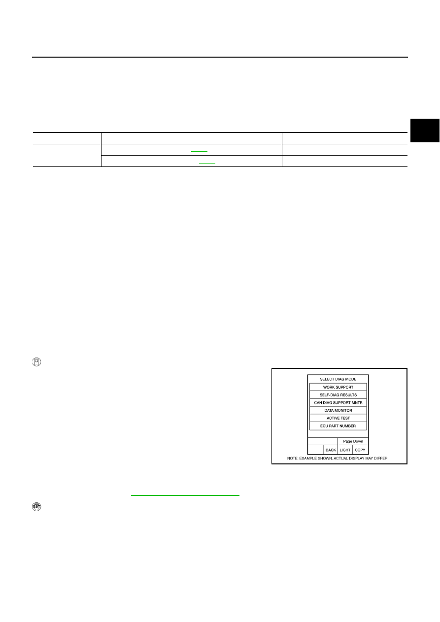
WITH CONSULT-II
1.
Turn ignition switch ON. (Do not start engine.)
2.
Select “SELECTION FROM MENU” in “DATA MONITOR” mode
for “A/T” with CONSULT-II and check monitor “ACCELE POSI”,
“SLCT LVR POSI” and “GEAR”.
3.
Touch “START”.
4.
Start engine.
5.
Drive vehicle and maintain the following conditions for at least 5
consecutive seconds.
ACCELE POSI: 1.5/8 - 2.0/8
SLCT LVR POSI: “D” position
GEAR: “3”
Þ
“4” (FR/B ON/OFF)
Driving location: Driving the vehicle uphill (increased engine load) will help maintain the driving
conditions required for this test.
6.
If DTC is detected go to
AT-146, "Diagnostic Procedure"
WITH GST
Follow the procedure “WITH CONSULT-II”.
Item name
Condition
Display value (Approx.)
FR/B SOLENOID
Front brake engaged. Refer to
0.6 - 0.8 A
Front brake disengaged. Refer to
.
0 - 0.05 A
BCIA0031E