Infiniti Q45. Manual - part 43


  Index      Infiniti     Infiniti Q45 - service repair manual 2006 year


Search            copyright infringement  


Content   ..  41  42  43  44   ..


Infiniti Q45. Manual - part 43


TROUBLE DIAGNOSIS

AT-85

D

E

F

G

H

I

J

K

L

M

A

B

AT

CONSULT-II Function (A/T)

NCS000UM

CONSULT-II can display each diagnostic item using the diagnostic test modes shown following.

FUNCTION

CONSULT-II REFERENCE VALUE

NOTICE:
1.

The CONSULT-II electrically displays shift timing and lock-up timing (that is, operation timing of each sole-
noid).
Check for time difference between actual shift timing and the CONSULT-II display. If the difference is
noticeable, mechanical parts (except solenoids, sensors, etc.) may be malfunctioning. Check mechanical
parts using applicable diagnostic procedures.

2.

Shift schedule (which implies gear position) displayed on CONSULT-II and that indicated in Service Man-
ual may differ slightly. This occurs because of the following reasons:

Actual shift schedule has more or less tolerance or allowance,

Shift schedule indicated in Service Manual refers to the point where shifts start, and

Gear position displayed on CONSULT-II indicates the point where shifts are completed.

3.

Display of solenoid valves on CONSULT-II changes at the start of shifting, while gear position is displayed
upon completion of shifting (which is computed by TCM).

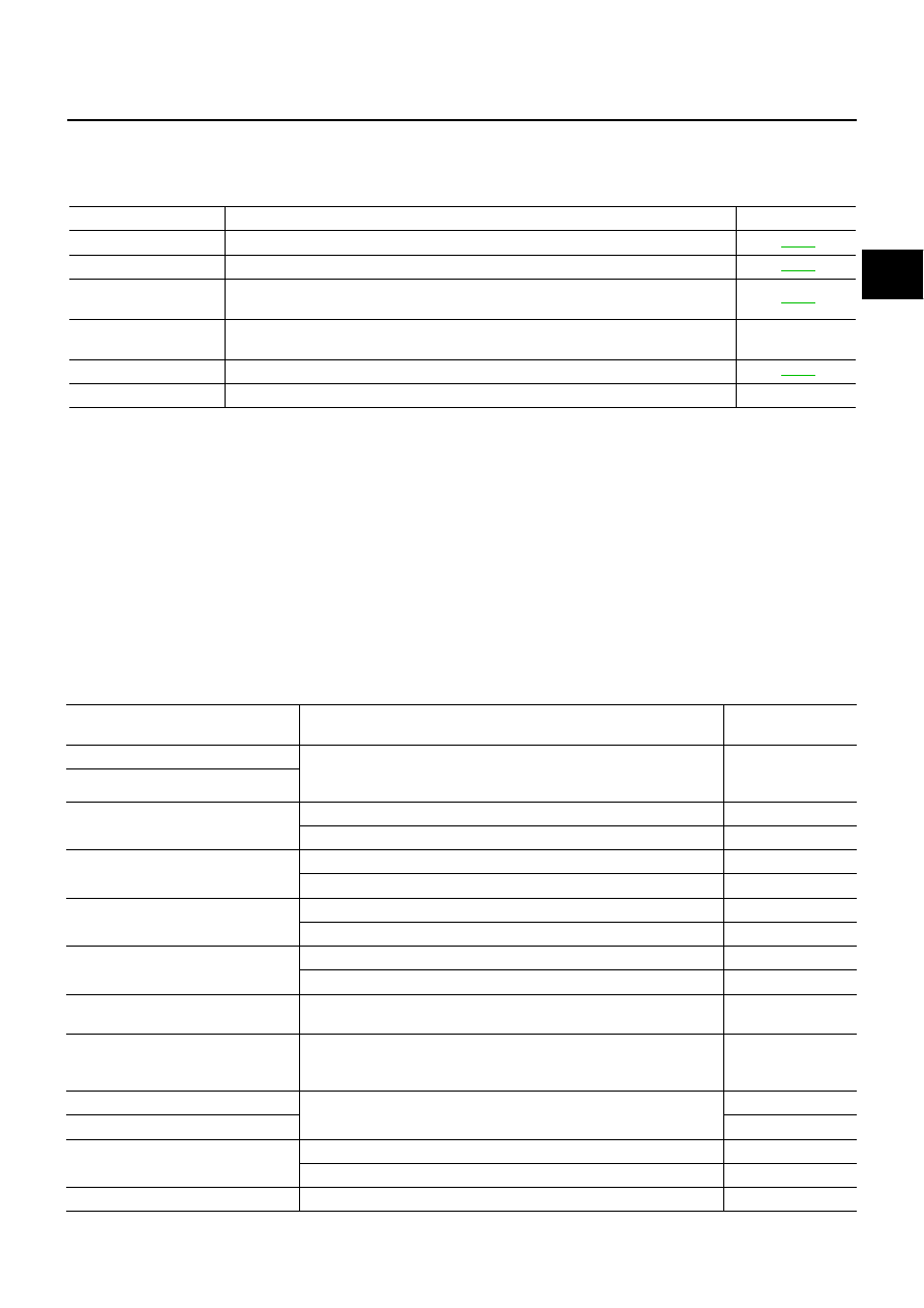
Diagnostic test mode

Function

Reference page

Self-diagnostic results

Self-diagnostic results can be read and erased quickly.

AT-87

Data monitor

Input/Output data in the TCM can be read.

AT-90

CAN diagnostic support 
monitor

The results of transmit/receive diagnosis of CAN communication can be read.

AT-94

Function test

Performed by CONSULT-II instead of a technician to determine whether each system 
is “OK” or “NG”.

DTC work support

Select the operating condition to confirm Diagnostic Trouble Codes.

AT-94

ECU part number

TCM part number can be read.

Item name

Condition 

Display value 

(Approx.)

VHCL/S SE-A/T

During driving

Approximately 
matches the speed-
ometer reading.

VHCL/S SE-MTR

ACCELE POSI

Released accelerator pedal.

0.0/8

Fully depressed accelerator pedal.

8.0/8

CLSD THL POS

Released accelerator pedal.

ON

Fully depressed accelerator pedal.

OFF

W/O THL POS

Fully depressed accelerator pedal.

ON

Released accelerator pedal.

OFF

BRAKE SW

Depressed brake pedal.

ON

Released brake pedal.

OFF

ENGINE SPEED

Engine running

Closely matches the 
tachometer reading.

TURBINE REV

During driving (lock-up ON)

Approximately 
matches the engine 
speed.

ATF TEMP SE 1

0

°

C (32

°

 F) - 20

°

C (68

°

F) - 80

°

C (176

°

F)

3.3 - 2.7 - 0.9 V

ATF TEMP SE 2

3.3 - 2.5 - 0.7 V

TCC SOLENOID

Slip lock-up is active

0.2 - 0.4 A

Lock-up is active

0.4 - 0.6 A

LINE PRES SOL

During driving

0.2 - 0.6 A

AT-86

TROUBLE DIAGNOSIS

FR/B SOLENOID

Front brake engaged. Refer to 

AT-19


.

0.6  -  0.8  A

Front brake disengaged. Refer to 

AT-19

 .

0 - 0.05 A

I/C SOLENOID

Input clutch disengaged. Refer to 

AT-19

 .

0.6 - 0.8 A

Input clutch engaged. Refer to 

AT-19

 .

0 - 0.05 A

D/C SOLENOID

Direct clutch disengaged. Refer to 

AT-19

 .

0.6 - 0.8 A

Direct clutch engaged. Refer to 

AT-19

 .

0 - 0.05 A

HLR/C SOL

High and low reverse clutch disengaged. Refer to 

AT-19

 .

0.6 - 0.8 A

High and low reverse clutch engaged. Refer to 

AT-19

 .

0 - 0.05 A

STARTER RELAY

Selector lever in “N”, “P” positions.

ON

Selector lever in other positions.

OFF

SLCT LVR POSI

Selector lever in “N”, “P” positions.

N/P

Selector lever in “R” position.

R

Selector lever in “D” position.

D

ON OFF SOL

Low coast brake engaged. Refer to 

AT-19


.

ON

Low coast brake disengaged. Refer to 

AT-19


.

OFF

ATF PRES SW 1

Front brake engaged. Refer to 

AT-19


.

ON

Front brake disengaged. Refer to 

AT-19


.

OFF

ATF PRES SW 2

Low coast brake engaged. Refer to 

AT-19


.

ON

Low coast brake disengaged. Refer to 

AT-19


.

OFF

ATF PRES SW 3

Input clutch engaged. Refer to 

AT-19


.

ON

Input clutch disengaged. Refer to 

AT-19


.

OFF

ATF PRES SW 5

Direct clutch engaged. Refer to 

AT-19


.

ON

Direct clutch disengaged. Refer to 

AT-19


.

OFF

ATF PRES SW 6

High and low reverse clutch engaged. Refer to 

AT-19


.

ON

High and low reverse clutch disengaged Refer to 

AT-19


.

OFF

MANU MODE SW

Manual shift gate position (neutral)

ON

Other than the above

OFF

NON M-MODE SW

Manual shift gate position

OFF

Other than the above

ON

UP SW LEVER

Selector lever: + side

ON

Other than the above

OFF

DOWN SW LEVER

Selector lever: - side

ON

Other than the above

OFF

GEAR

During driving

1, 2, 3, 4, 5

Item name

Condition 

Display value 

(Approx.)

TROUBLE DIAGNOSIS

AT-87

D

E

F

G

H

I

J

K

L

M

A

B

AT

CONSULT-II SETTING PROCEDURE

Refer to 

GI-36, "CONSULT-II Start Procedure"

 .

SELF-DIAGNOSTIC RESULT MODE

After performing self-diagnosis, place check marks for results on the 

AT-46, "DIAGNOSTIC WORKSHEET"

 .

Reference pages are provided following the items.

Operation Procedure

1.

Touch “SELF-DIAG RESULTS” on “SELECT DIAG MODE”
screen.
Display shows malfunction experienced since the last erasing
operation.

Display Items List

X: Applicable, —: Not applicable

BCIA0031E

Items (CONSULT-

II screen terms)

Malfunction is detected when...

TCM self-

diagnosis

OBD-II (DTC)

Reference 

page

 “A/T” with   

CONSULT-II

MIL indicator 

lamp*1, 

“ENGINE” with 

CONSULT-II or 

GST

CAN COMM CIR-
CUIT

When a malfunction is detected in CAN communications.

U1000

U1000

AT-99

STARTER RELAY/
CIRC

If this signal is ON other than in “P” or “N” position, this is 
judged to be a malfunction.
(And if it is OFF in “P” or “N” position, this too is judged to 
be a malfunction.)

P0615

AT-102

TCM

TCM is malfunctioning

P0700

P0700

AT-106

PNP SW/CIRC

PNP switch 1-4 signals input with impossible pattern.

“P” position is detected from “N” position without any other 
positions being detected in between.

P0705

P0705

AT-107

TURBINE REV S/
CIRC

TCM does not receive the proper voltage signal from the 
sensor.

TCM detects an irregularity only at position of 4th gear for 
turbine revolution sensor 2.

P0717

P0717

AT-111

VEH SPD SEN/
CIR AT

Signal from vehicle speed sensor A/T (Revolution sensor) 
not input due to cut line or the like.

Unexpected signal input during running.

After ignition switch is turned ON, unexpected signal input 
from vehicle speed sensor MTR before the vehicle starts 
moving.

P0720

P0720

AT-113

ENGINE SPEED 
SIG

TCM does not receive the CAN communication signal from 
the ECM.

P0725

AT-118

TCC SOLENOID/
CIRC

Normal voltage not applied to solenoid due to cut line, 
short, or the like.

P0740

P0740

AT-120

A/T TCC S/V 
FNCTN

A/T cannot perform lock-up even if electrical circuit is good.

TCM detects as irregular by comparing difference value 
with slip rotation.

P0744

P0744*2

AT-122

AT-88

TROUBLE DIAGNOSIS

L/PRESS SOL/
CIRC

Normal voltage not applied to solenoid due to cut line, 
short, or the like.

TCM detects as irregular by comparing target value with 
monitor value.

P0745

P0745

AT-124

TP SEN/CIRC A/T

TCM does not receive the proper accelerator pedal position 
signals (input by CAN communication) from ECM.

P1705

AT-126

ATF TEMP SEN/
CIRC

 During running, the A/T fluid temperature sensor signal 
voltage is excessively high or low.

P1710

P0710

AT-129

VEH SPD SE/CIR-
MTR

Signal (CAN communication) from vehicle speed sensor 
MTR not input due to cut line or the like.

Unexpected signal input during running.

P1721

AT-134

A/T INTERLOCK

Except during shift change, the gear position and ATF pres-
sure switch states are monitored and comparative judge-
ment made.

P1730

P1730

AT-136

A/T 1ST E/BRAK-
ING

Each ATF pressure switch and solenoid current is moni-
tored and if a pattern is detected having engine braking 1st 
gear other than in the M1 position, a malfunction is 
detected.

P1731

AT-139

I/C SOLENOID/
CIRC

Normal voltage not applied to solenoid due to functional 
malfunction, cut line, short, or the like.

TCM detects as irregular by comparing target value with 
monitor value.

P1752

P1752

AT-141

I/C SOLENOID 
FNCTN 

TCM detects that actual gear ratio is irregular, and relation 
between gear position and condition of ATF pressure 
switch 3 is irregular during depressing accelerator pedal. 
(Other than during shift change.)

TCM detects that relation between gear position and condi-
tion of ATF pressure switch 3 is irregular during releasing 
accelerator pedal. (Other than during shift change.)

P1754

P1754*2

AT-143

FR/B SOLENOID/
CIRC

Normal voltage not applied to solenoid due to functional 
malfunction, cut line, short, or the like.

TCM detects as irregular by comparing target value with 
monitor value.

P1757

P1757

AT-145

FR/B SOLENOID 
FNCT

TCM detects that actual gear ratio is irregular, and relation 
between gear position and condition of ATF pressure 
switch 1 is irregular during depressing accelerator pedal. 
(Other than during shift change.)

TCM detects that relation between gear position and condi-
tion of ATF pressure switch 1 is irregular during releasing 
accelerator pedal. (Other than during shift change.)

P1759

P1759*2

AT-147

D/C SOLENOID/
CIRC

Normal voltage not applied to solenoid due to cut line, 
short, or the like.

TCM detects as irregular by comparing target value with 
monitor value.

P1762

P1762

AT-149

Items (CONSULT-

II screen terms)

Malfunction is detected when...

TCM self-

diagnosis

OBD-II (DTC)

Reference 

page

 “A/T” with   

CONSULT-II

MIL indicator 

lamp*1, 

“ENGINE” with 

CONSULT-II or 

GST


Content   ..  41  42  43  44   ..