Infiniti Q45. Manual - part 37
TROUBLE DIAGNOSIS
AT-61
D
E
F
G
H
I
J
K
L
M
A
B
AT
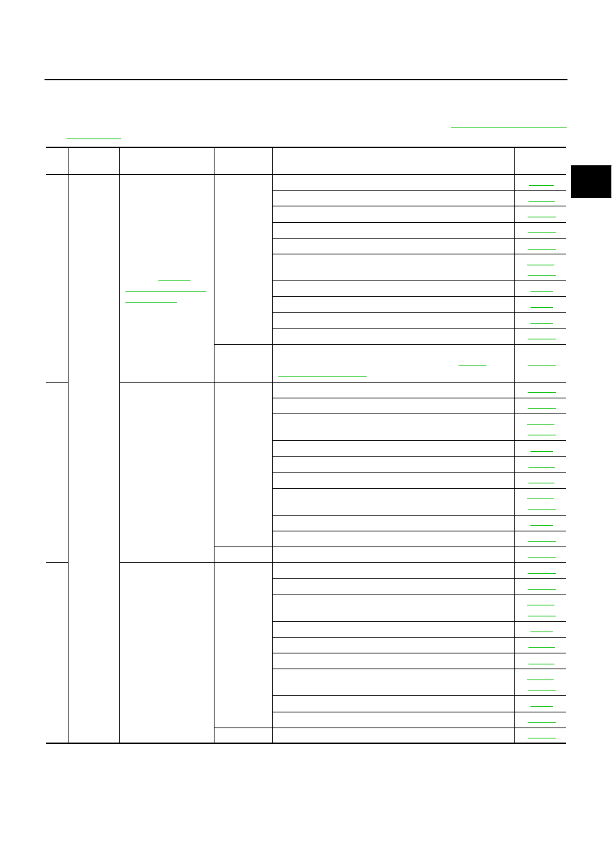
Symptom Chart
NCS000UK
●
The diagnostics item numbers show the sequence for inspection. Inspect in order from Item 1.
●
Overhaul and inspection inside the A/T only if A/T fluid condition is NG. Refer to
No.
Items
Symptom
Condition
Diagnostic Item
Reference
page
1
Shift
Shock
Large shock. (“N”
→
"Large Shock (“N” to
“D” Position)"
ON vehicle
1. Engine idle speed
2. Engine speed signal
3. Accelerator pedal position sensor
4. A/T position
5. A/T fluid temperature sensor
6. ATF pressure switch 1 and front brake solenoid valve
7. CAN communication line
8. A/T fluid level and state
9. Line pressure test
10. Control valve with TCM
OFF vehicle
11. Forward brake (Parts behind drum support is impossible
to perform inspection by disassembly. Refer to
2
Shock is too large
when changing D
1
→
D
2
or M
1
→
M
2
.
ON vehicle
1. Accelerator pedal position sensor
2. A/T position
3. ATF pressure switch 5 and direct clutch solenoid valve
4. CAN communication line
5. Engine speed signal
6. Turbine revolution sensor
7. Vehicle speed sensor·A/T and vehicle speed sensor·MTR
8. A/T fluid level and state
9. Control valve with TCM
OFF vehicle
10. Direct clutch
3
Shock is too large
when changing D
2
→
D
3
or M
2
→
M
3
.
ON vehicle
1. Accelerator pedal position sensor
2. A/T position
3. ATF pressure switch 6, high and low reverse clutch sole-
noid valve
4. CAN communication line
5. Engine speed signal
6. Turbine revolution sensor
7. Vehicle speed sensor·A/T and vehicle speed sensor·MTR
8. A/T fluid level and state
9. Control valve with TCM
OFF vehicle
10. High and low reverse clutch