Infiniti Q45. Manual - part 6
 

  Index      Infiniti     Infiniti Q45 - service repair manual 2006 year


Search            copyright infringement  


Content   ..  4  5  6  7   ..


Infiniti Q45. Manual - part 6


LASER BEAM AIMING ADJUSTMENT

ACS-17

[ICC]

C

D

E

F

G

H

I

J

L

M

A

B

ACS

6.

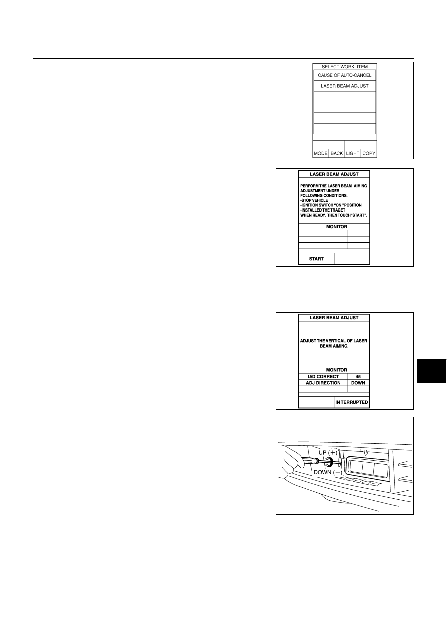
Touch “LASER BEAM ADJUST” on “SELECT WORK ITEM”
screen.

7.

Touch “START”.

CAUTION:

If the adjustment screen does not appear on the CONSULT-
II screen in 10 seconds. After touching “LASER BEAM
ADJUST” screen, the following causes may be considered:

●

Target is not set accurately.

●

There is not enough space beside the target.

●

The range of laser beam aiming exceeds for improper
installation position.

–

Deformation of vehicle body.

–

Deformation of unit.

–

Deformation of bracket.

●

The area is not suitable for the adjustment work.

●

ICC sensor is not clean.

8.

After the CONSULT-II displays “ADJUST THE VERTICAL OF
LASER BEAM AIMING” turn the up-down direction adjusting
screw until “U/D CORRECT” value is set in the range of 

±

4.

CAUTION:

Turn the screw slowly. The value change on display is
slower than actual movement of the ICC sensor. Wait for 2
seconds every time the screw is turned half a rotation.
NOTE:
Turning the screw clockwise to laser beam is downward and
counterclockwise to laser beam is upward.

9.

When “U/D CORRECT” value indicates 

±

4, confirm that the margin of value remains within 

±

4 at least for

2 seconds with no equipment or hand touching the ICC sensor. 

SKIA6191E

SKIA1220E

SKIA1221E

PKIA9671E

ACS-18

[ICC]

LASER BEAM AIMING ADJUSTMENT

When “COMPLETED THE VERTICAL AIMING OF LASER
BEAM” appears on screen, touch “END”.

CAUTION:

Be sure that the margin of “U/D CORRECT” is within 

±

4 with

ICC sensor unit is untouched.

10. Confirm that “ADJUSTING AUTOMATIC HORIZONTAL LASER

BEAM AIMING” is on screen and wait for a while. (maximum: 10
seconds.)

11. Confirm that “NORMALLY COMPLETED” is displayed on CON-

SULT-II and close the aiming adjustment procedure by touching
“END”.

CAUTION:

Complete all the procedures once “LASER BEAM ADJUST”
mode is entered in CONSULT-II. When the procedure is dis-
continued, the ICC system is inoperable.

CHECK AFTER THE ADJUSTMENT

Test the ICC system operation by running test. Refer to 

ACS-11, "ICC System Running Test"

 .

SKIA1223E

SKIA1224E

SKIA1225E

ELECTRICAL UNITS LOCATION

ACS-19

[ICC]

C

D

E

F

G

H

I

J

L

M

A

B

ACS

ELECTRICAL UNITS LOCATION

PFP:25230

Component Parts and Harness Connector Location

NKS001K5

PKIC5176E

ACS-20

[ICC]

WIRING DIAGRAM

WIRING DIAGRAM

PFP:00000

Schematic

NKS001K6

TKWM3833E


Content   ..  4  5  6  7   ..