Infiniti Q45 (FY33). Manual - part 493


  Index      Infiniti     Infiniti Q45 (FY33) - service repair manual 2001 year


Search            copyright infringement  


Content   ..  491  492  493  494   ..


Infiniti Q45 (FY33). Manual - part 493


RHA124F

I

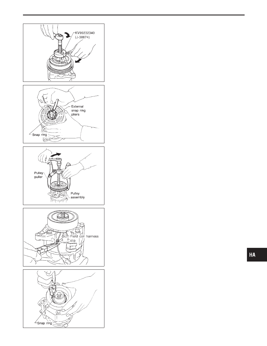
Remove the clutch disc using the clutch disc puller.
Insert the holder’s three pins into the holes in the clutch disc.
Rotate the holder clockwise to hook it onto the plate. Then,
tighten the center bolt to remove the clutch disc.
After removing the clutch disc, remove the shims from either
the drive shaft or the clutch disc.

RHA138E

I

Remove the snap ring using external snap ring pliers.

RHA139E

I

Pulley removal
Position the center pulley puller on the end of the drive shaft,
and remove the pulley assembly using any commercially avail-
able pulley puller.
To prevent the pulley groove from being deformed, the
puller claws should be positioned onto the edge of the
pulley assembly.

RHA125F

I

Remove the field coil harness clip using a pair of pliers.

RHA145E

I

Remove the snap ring using external snap ring pliers.

GI

MA

EM

LC

EC

FE

AT

PD

FA

RA

BR

ST

RS

BT

EL

IDX

SERVICE PROCEDURES

Compressor Clutch (Cont’d)

HA-137

RHA126F

RHA142E

INSPECTION

Clutch disc

If the contact surface shows signs of damage due to excessive
heat, replace clutch disc and pulley.

Pulley

Check the appearance of the pulley assembly. If the contact sur-
face of pulley shows signs of excessive grooving, replace clutch
disc and pulley. The contact surfaces of the pulley assembly should
be cleaned with a suitable solvent before reinstallation.

Coil

Check coil for loose connection or cracked insulation.

INSTALLATION

I

Install the field coil.

Be sure to align the coil’s pin with the hole in the
compressor’s front head.

I

Install the field coil harness clip using a screwdriver.

RHA143EA

I

Install the pulley assembly using the installer and a hand
press, and then install the snap ring using snap ring pliers.

RHA127F

I

Install the clutch disc on the drive shaft, together with the
original shim(s). Press the clutch disc down by hand.

RHA086E

I

Using the holder to prevent clutch disc rotation, tighten the bolt
to 14 N

m (1.4 kg-m, 10 ft-lb) torque.

After tightening the bolt, check that the pulley rotates
smoothly.

SERVICE PROCEDURES

Compressor Clutch (Cont’d)

HA-138

RHA087E

I

Check clearance around the entire periphery of clutch disc.

Disc-to-pulley clearance:

0.3 - 0.6 mm (0.012 - 0.024 in)

If the specified clearance is not obtained, replace adjusting
spacer and readjust.

BREAK-IN OPERATION

When replacing compressor clutch assembly, always carry out the
break-in operation. This is done by engaging and disengaging the
clutch about thirty times. Break-in operation raises the level of
transmitted torque.

RHA042GA

Ventilation Air Filter

FUNCTION

Air inside passenger compartment is kept clean at either recircula-
tion or fresh mode by installing ventilation air filter into cooling unit.

SHA192F

REPLACEMENT PROCEDURES

1.

Remove undercover.

2.

Remove glove box.

3.

Remove instrument reinforcement from instrument panel.

4.

Remove ventilation air filter fixed clip.

5.

Take out the lower side ventilation air filter from cooling unit.

6.

Then slide upper side filter to the bottom position and take off
the ventilation air filter from the cooling unit.

7.

Replace with new one and reinstall on cooling unit.

8.

Reinstall instrument reinforcement, glove box and undercover.

GI

MA

EM

LC

EC

FE

AT

PD

FA

RA

BR

ST

RS

BT

EL

IDX

SERVICE PROCEDURES

Compressor Clutch (Cont’d)

HA-139

General Specifications

COMPRESSOR

Model

CALSONIC make

V-6

Type

V-6 variable displacement

Displacement

cm

3

(cu in)/rev.

Max.

184 (11.228)

Min.

10.5 (0.641)

Cylinder bore x stroke

mm (in)

37 (1.46)

x [1.6 - 28.6 (0.063 - 1.126)]

Direction of rotation

Clockwise

(viewed from drive end)

Drive belt

Poly V

LUBRICANT

Model

CALSONIC make

V-6

Name

Nissan A/C System Oil

Type S

Part number

KLH00-PAGS0

Capacity

m


(US fl oz, Imp fl oz)

Total in system

200 (6.8, 7.0)

Compressor (Service part)
charging amount

200 (6.8, 7.0)

REFRIGERANT

Type

HFC-134a (R-134a)

Capacity

kg (lb)

0.675 - 0.725 (1.488 - 1.599)

Inspection and Adjustment

ENGINE IDLING SPEED (When A/C is ON)

I

Refer to EC section.

BELT TENSION

I

Refer to Checking Drive Belts (MA section).

SERVICE DATA AND SPECIFICATIONS (SDS)

HA-140


Content   ..  491  492  493  494   ..