Infiniti Q45 (FY33). Manual - part 415
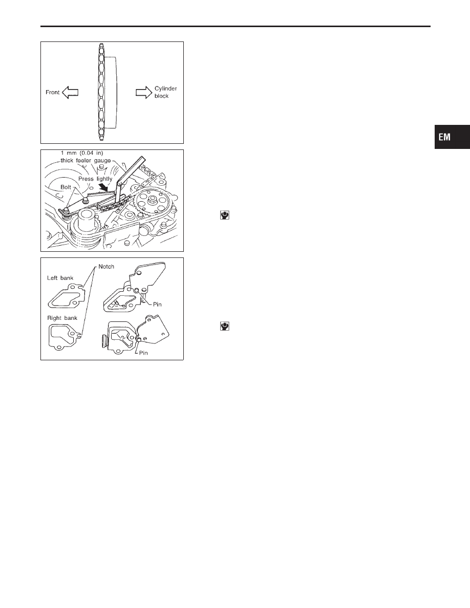
SEM475F
7.
Install oil pump drive chain.
I
Install oil pump drive sprocket on crankshaft side with boss
side facing cylinder block.
SEM476F
8.
Install the upper and lower oil pump drive chain guides.
Install the upper guide as follows.
a.
Install the lower side.
b.
Loosely tighten bolts on upper side.
c.
Insert 1 mm (0.04 in) feeler gauge between guide and chain.
Press the guide lightly on the chain side with the same force
as the guide weight and tighten installation bolts.
: 6.3 - 8.3 N
⋅
m (0.64 - 0.85 kg-m, 55.6 - 73.8 in-lb)
SEM477F
9.
Install chain tensioner.
I
Always replace gasket with new part.
I
Install gasket by pressing the notch on pin connecting chain
tensioner to plate.
Be careful not to bend gasket during installation.
I
Install with pins inserted.
Tighten bolts to specified tightening torque.
: 9.2 - 10.8 N
⋅
m (0.94 - 1.1 kg-m, 81.6 - 95.5 in-lb)
I
Lubricate timing chain and sliding parts with engine oil.
GI
MA
LC
EC
FE
AT
PD
FA
RA
BR
ST
RS
BT
HA
EL
IDX
TIMING CHAIN
Installation (Cont’d)
EM-21