Infiniti Q45 (FY33). Manual - part 127


  Index      Infiniti     Infiniti Q45 (FY33) - service repair manual 2001 year


Search            copyright infringement  


Content   ..  125  126  127  128   ..


Infiniti Q45 (FY33). Manual - part 127


SEF394X

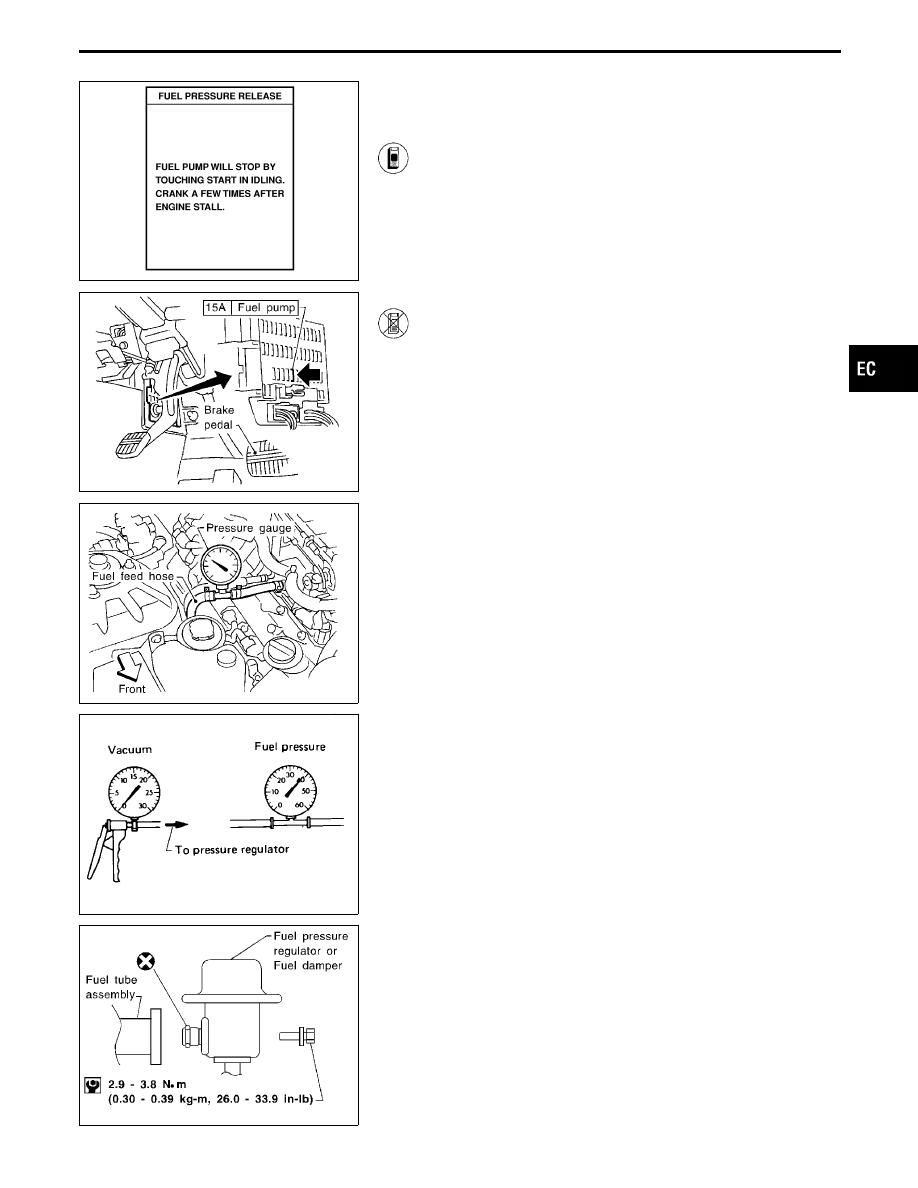
Fuel Pressure Release

Before disconnecting fuel line, release fuel pressure from fuel
line to eliminate danger.

1.

Start engine.

2.

Perform “FUEL PRESSURE RELEASE” in “WORK
SUPPORT” mode with CONSULT-II.
(Touch “START” and after engine stalls, crank it two or
three times to release all fuel pressure.)

3.

Turn ignition switch off.

SEF111T

------------------------------------------------------------------------------------------------------------------------------------------------------------------------------------------------------------------------------------------------------ OR ------------------------------------------------------------------------------------------------------------------------------------------------------------------------------------------------------------------------------------------------------

1.

Remove fuse for fuel pump.

2.

Start engine.

3.

After engine stalls, crank it two or three times to release
all fuel pressure.

4.

Turn ignition switch off and reconnect fuel pump fuse.

SEF112T

Fuel Pressure Check

I

When reconnecting fuel line, always use new clamps.

I

Make sure that clamp screw does not contact adjacent
parts.

I

Use a torque driver to tighten clamps.

I

Use Pressure Gauge to check fuel pressure.

1.

Release fuel pressure to zero, refer to previous page.

2.

Disconnect fuel hose between fuel filter and fuel tube (engine
side).

3.

Install pressure gauge between fuel filter and fuel tube.

4.

Start engine and check for fuel leakage.

SEF718B

5.

Read the indication of fuel pressure gauge.

At idling:

Approximately 235 kPa (2.4 kg/cm

2

, 34 psi)

A few seconds after ignition switch is turned OFF to
ON:

Approximately 294 kPa (3.0 kg/cm

2

, 43 psi)

6.

Stop engine and disconnect fuel pressure regulator vacuum
hose from intake manifold.

7.

Plug intake manifold with a rubber cap.

8.

Connect variable vacuum source to fuel pressure regulator.

SEF114T

9.

Start engine and read indication of fuel pressure gauge as
vacuum is changed.

Fuel pressure should decrease as vacuum increases. If results
are unsatisfactory, replace fuel pressure regulator.

GI

MA

EM

LC

FE

AT

PD

FA

RA

BR

ST

RS

BT

HA

EL

IDX

BASIC SERVICE PROCEDURE

EC-37

Injector Removal and Installation

SEF113T

SEF245QB

1.

Release fuel pressure to zero, refer to previous page.

2.

Remove intake manifold collector. Refer to EM section (“TIM-
ING CHAIN”).

3.

Disconnect vacuum hose from pressure regulator.

4.

Disconnect fuel hoses from fuel tube assembly.

I

Do not disassemble fuel tube assembly.

5.

Disconnect injector harness connectors.

6.

Remove injectors with fuel tube assembly.

I

Push injector tail piece.

I

Do not pull on the connector.

7.

Push out any malfunctioning injector from fuel tube assembly.

8.

Replace or clean injector as necessary.

9.

Install injector to fuel tube assembly.

I

Always replace O-rings with new ones.

I

Lubricate O-rings with a smear of engine oil.

10. Install injectors with fuel tube assembly to intake manifold.
Tighten in numerical order shown in the figure.
a)

First, tighten all bolts to 9.3 to 10.8 N

m (0.95 to 1.1 kg-m, 6.9

to 8.0 ft-lb).

b)

Then, tighten all bolts to 21 to 26 N

m (2.1 to 2.7 kg-m, 15 to

20 ft-lb).

11. Install fuel hoses to fuel tube assembly.
12. Reinstall any parts removed in reverse order of removal.

CAUTION:

After properly connecting fuel hose to injector and fuel tube
assembly, check connection for fuel leakage.

BASIC SERVICE PROCEDURE

EC-38

SEF910X

Throttle Opener

INSPECTION

1.

Start engine and let it idle.

2.

Confirm the amount of the rod moves “L” more than 1.65 mm
(0.0650 in), the throttle drum becomes free from the rod of the
throttle opener.

If NG, go to next step.
If OK, inspection is end.

SEF109L

SEF368U

3.

Turn ignition switch “OFF”.

4.

Check vacuum source to throttle opener.

a.

Check vacuum hose for disconnection or improper connection.

b.

Remove vacuum hose connected to throttle opener.

c.

Attach a vacuum gauge to vacuum hose, which is discon-
nected.

d.

Start engine and let it idle.

e.

Make sure that the vacuum is more than −40.0 kPa (−300
mmHg, −11.81 inHg).

f.

Remove the vacuum gauge from intake manifold.
If NG, go to next step.
If OK, go to step 7.

5.

Check vacuum hose for clogging and cracks.
If NG, replace or clean vacuum hose.
If OK, go to next step.

6.

Blow air into the intake manifold and make sure air flows freely.
If NG, replace or clean intake manifold.
If OK, go to next step.

SEF793W

7.

Check throttle opener.

a.

Connect suitable vacuum hose to vacuum pump as shown at
left.

b.

Apply vacuum [more than −40.0 kPa (−300 mmHg, −11.81
inHg)] until the throttle drum becomes free from the rod of the
throttle opener.

c.

Confirm the amount of the rod moves more than 1.65 mm
(0.0650 in), and also the throttle drum becomes free from the
rod of the throttle opener.
If NG, go to next step.

8.

Check visually for cracking and/or distortion of throttle opener
and rod.
If NG, replace throttle opener.
If OK, install the vacuum hose and repeat from step 1 to 2.

GI

MA

EM

LC

FE

AT

PD

FA

RA

BR

ST

RS

BT

HA

EL

IDX

BASIC SERVICE PROCEDURE

EC-39

Fast Idle Cam (FIC) Inspection and Adjustment

1.

Remove throttle body from engine.

2.

Wait for at least 3 hours.
(This step is necessary to bring the temperature of the thermo-
element to the room temperature

SEF292TA

3.

Measure thermo-element stroke (L) and room temperature.

4.

Check thermo-element stroke (L) as shown in the figure.

CAUTION:

Do not adjust TAS.

L: Thermo-element stroke

Judgement

Within oblique line

Thermo-element is normal

,

Adjust

FI cam (go to step 5).

Out of oblique line

Replace thermo-element

,

Adjust FI

cam (go to step 2).

SEF293T

5.

Measure clearance between stopper and throttle adjusting
screw (TAS) as shown in the figure. If out of specification,
adjust the clearance using adjusting screw.

CAUTION:

Do not adjust throttle adjusting screw (TAS).
6.

After adjustment, tighten lock nut of adjusting screw.

: 1.5 - 2.0 N

m (0.15 - 0.2 kg-m, 13.0 - 17.4 in-lb)

7.

Reinstall throttle body.

8.

After warming up engine, check that there is a clearance
between FI cam and roller.

SEF294T

SEF392X

Direct Ignition System — How to Check Idle
Speed and Ignition Timing

IDLE SPEED

I

Method A (Using CONSULT-II)

Check idle speed in “DATA MONITOR” mode with CONSULT-II.

BASIC SERVICE PROCEDURE

EC-40


Content   ..  125  126  127  128   ..