Infiniti Q45 (FY33). Manual - part 90
SBR576E
SBR640D
GI
MA
EM
LC
EC
FE
AT
PD
FA
RA
ST
RS
BT
HA
EL
IDX
TROUBLE DIAGNOSES
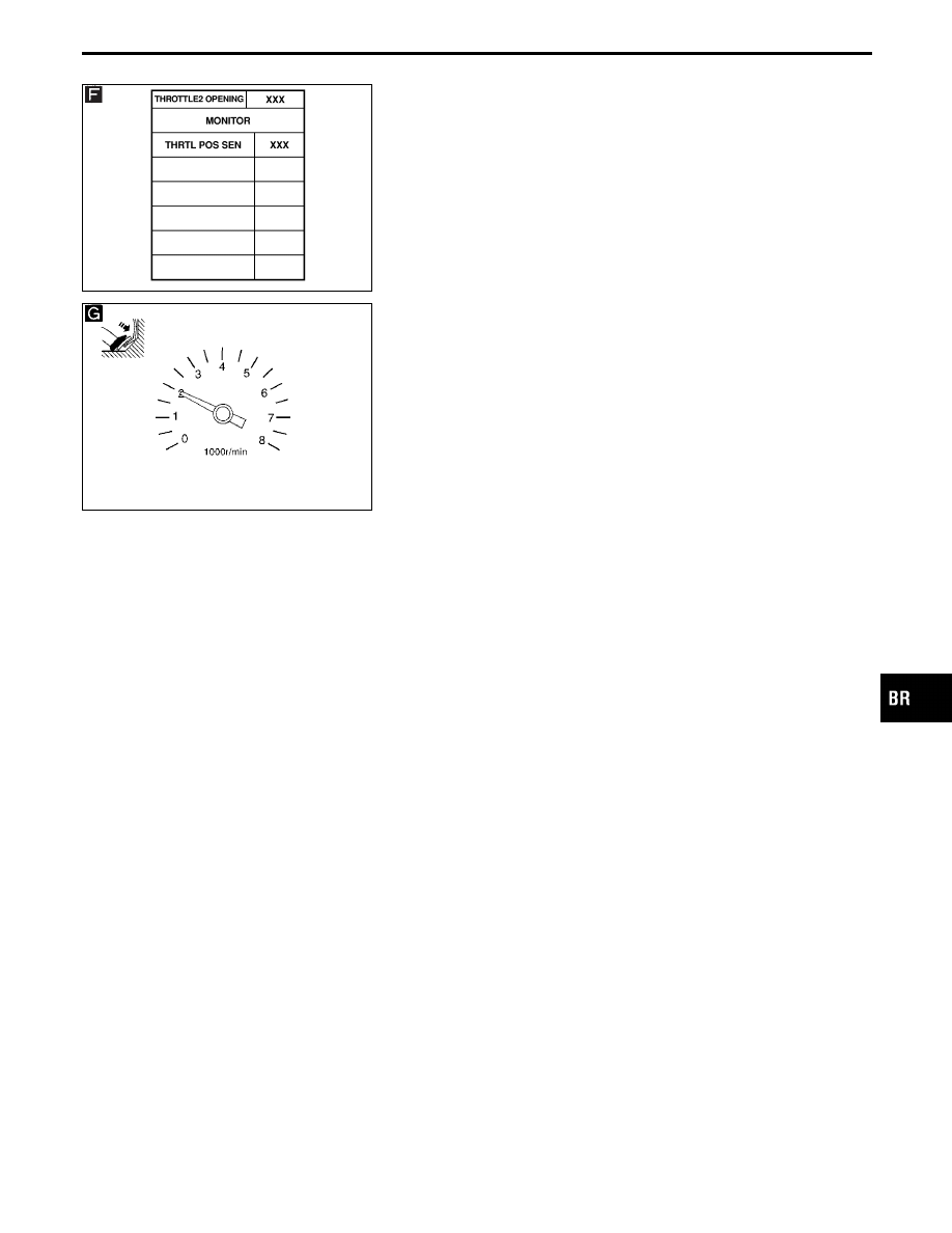
CONSULT-II Inspection Procedure for TAC
Module (Cont’d)
BR-77
|
|
|
SBR576E SBR640D GI MA EM LC EC FE AT PD FA RA ST RS BT HA EL IDX TROUBLE DIAGNOSES CONSULT-II Inspection Procedure for TAC BR-77 |