Infiniti Q45 (FY33). Manual - part 23
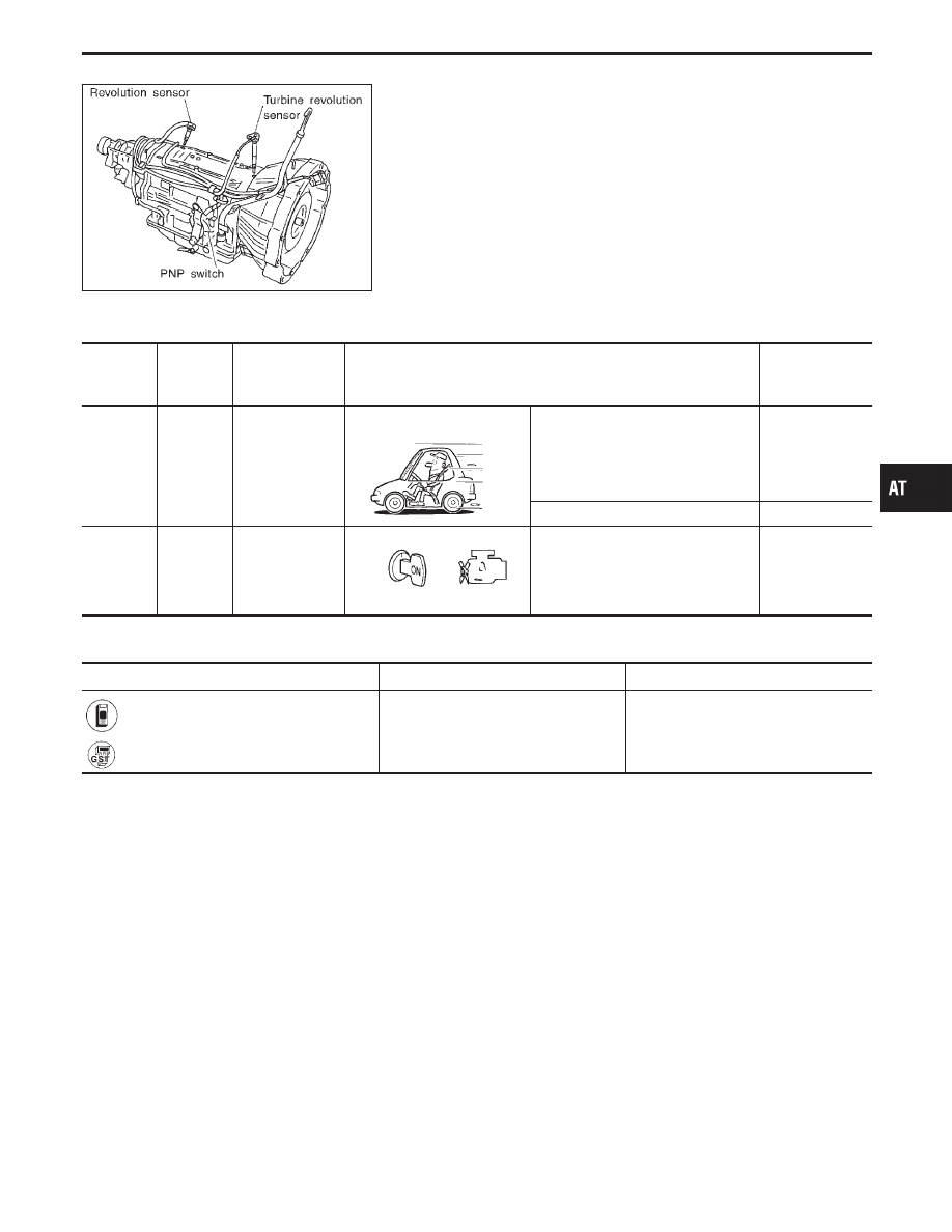
SAT557IA
Vehicle Speed Sensor
⋅
A/T (Revolution sensor)
DESCRIPTION
The revolution sensor detects the revolution of the output shaft
parking pawl lock gear and emits a pulse signal. The pulse signal
is sent to the TCM which converts it into vehicle speed.
TCM TERMINALS AND REFERENCE VALUE
Remarks: Specification data are reference values.
Terminal
No.
Wire color
Item
Condition
Judgement
standard
(Approx.)
25
W
Revolution sen-
sor
(Measure in AC
range)
When vehicle cruises at 30 km/h (19
MPH).
1V or more
Voltage rises
gradually in
response to
vehicle speed.
When vehicle parks.
0V
35
B
Throttle position
sensor
(Ground)
—
0V
ON BOARD DIAGNOSIS LOGIC
Diagnostic trouble code
Malfunction is detected when ...
Check item (Possible cause)
: VEH SPD SEN/CIR AT
TCM does not receive the proper volt-
age signal from the sensor.
I
Harness or connectors
(The sensor circuit is open or
shorted.)
I
Revolution sensor
: P0720
GI
MA
EM
LC
EC
FE
PD
FA
RA
BR
ST
RS
BT
HA
EL
IDX
TROUBLE DIAGNOSIS FOR DTC P0720
AT-89