Infiniti Q45 (FY33). Manual - part 2
SEF289H
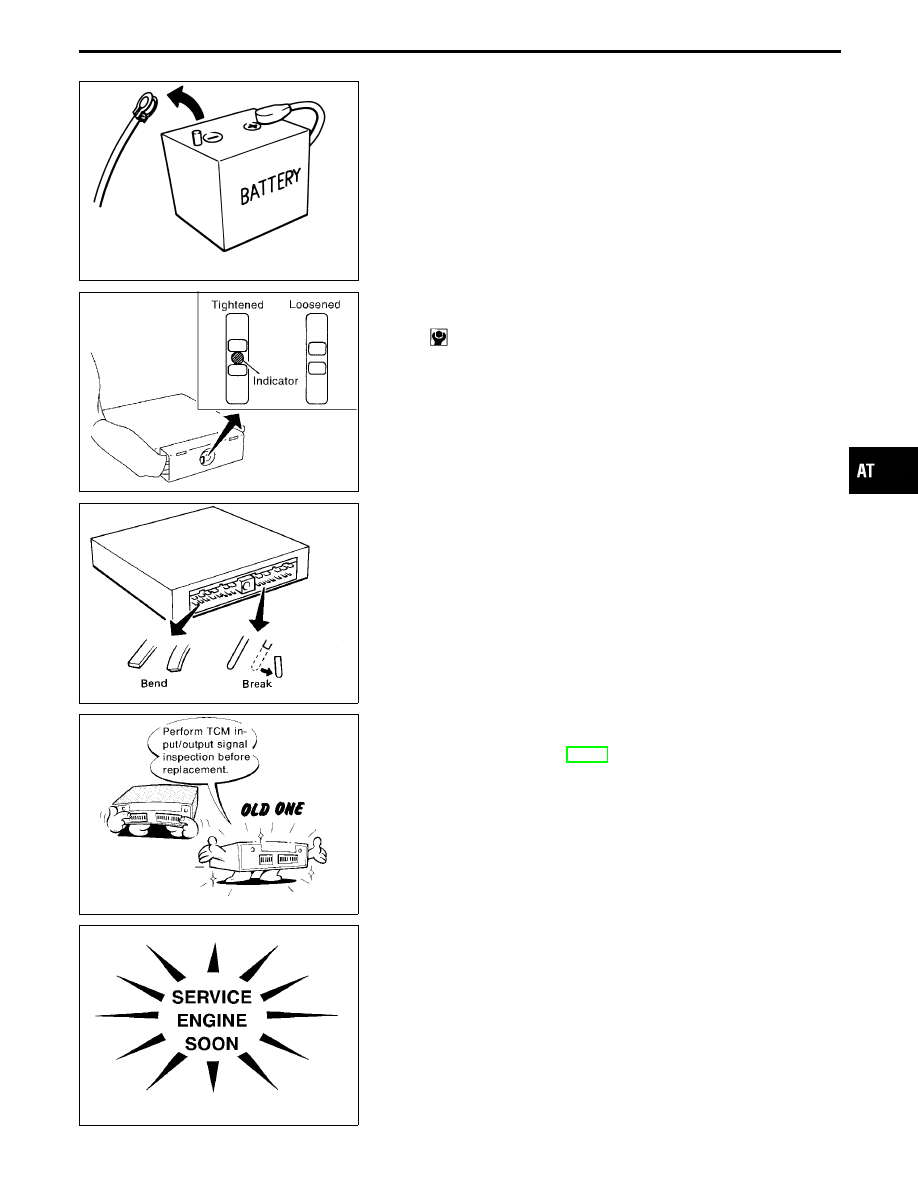
Precautions
I
Before connecting or disconnecting the TCM harness
connector, turn ignition switch OFF and disconnect nega-
tive battery terminal. Failure to do so may damage the
TCM. Because battery voltage is applied to TCM even if
ignition switch is turned off.
SAT973I
I
When connecting TCM harness connector, tighten secur-
ing bolt until the orange indicator appears.
: 3 - 5 N
⋅
m (0.3 - 0.5 kg-m, 26 - 43 in-lb)
SEF291H
I
When connecting or disconnecting pin connectors into or
from TCM, take care not to damage pin terminals (bend or
break).
Make sure that there are not any bends or breaks on TCM
pin terminal, when connecting pin connectors.
MEF040DA
I
Before replacing TCM, perform TCM input/output signal
inspection and make sure whether TCM functions prop-
erly or not. (Refer to AT-77.)
SAT964I
I
After performing each TROUBLE DIAGNOSIS, perform
“DTC (Diagnostic Trouble Code) CONFIRMATION PROCE-
DURE”.
The DTC should not be displayed in the “DTC CONFIRMA-
TION PROCEDURE” if the repair is completed.
GI
MA
EM
LC
EC
FE
PD
FA
RA
BR
ST
RS
BT
HA
EL
IDX
PRECAUTIONS AND PREPARATION
AT-5